by Adaptify Support | Jun 22, 2026 | Power Grid Articles
What Is Electricity from the Grid — and How Does It Reach You?
Electricity from the grid travels through one of the most complex engineering systems ever built — from a power plant, through hundreds of miles of transmission lines, and into your home or facility in a fraction of a second.
Here’s a quick overview of how it works:
| Stage |
What Happens |
| Generation |
Power plants convert fuel or natural forces into electrical energy |
| Step-Up |
Transformers raise voltage to 115,000–765,000 volts for long-distance travel |
| Transmission |
High-voltage lines carry power across hundreds of miles with minimal loss |
| Step-Down |
Substations reduce voltage to safer levels for local delivery |
| Distribution |
Lower-voltage lines carry power to homes and businesses |
| Meter |
Your usage is measured and billed by a utility |
The U.S. grid alone spans thousands of miles of high-voltage lines and millions of miles of lower-voltage lines, connecting thousands of power plants to hundreds of millions of customers. It is, by almost any measure, the largest machine ever built.
Yet most people never think about it — until the lights go out.
Grid reliability failures make the scale of this system impossible to ignore. In February 2021, nearly 10 million people in Texas lost power during a severe winter storm, resulting in more than 50 deaths. Events like that reveal just how much modern life depends on a steady, uninterrupted flow of electricity from grid infrastructure.
I’m Bill French, Sr., Founder and CEO of FDE Hydro™, and my five decades in heavy civil construction — including work selected by the U.S. Department of Energy’s Water Power Technology Office — have given me a front-row seat to how clean energy and electricity from the grid are being reshaped by modular innovation. In this guide, I’ll break down exactly how the grid works, what threatens it, and where it’s headed.
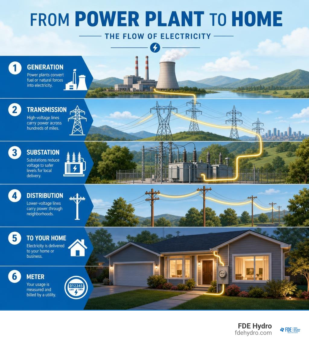
Electricity from grid vocab explained:
The Architecture of Power: How the Grid is Structured
To understand how we get electricity from grid utilities, we first need to look at the physical architecture. The electrical grid is not a single, unified machine. Instead, it is a vast network of generation facilities, high-voltage pathways, substations, and local distribution lines.
Historically, this system was designed for one-way traffic: massive, centralized power plants burned coal, gas, or harnessed nuclear and hydro energy, sending that power outward to passive consumers. Today, the network is shifting toward a decentralized, two-way system where consumers also feed power back into the system.
For a deeper dive into what “the grid” actually means mathematically and structurally, check out our guide on Unplugging the Mystery What Does Grid Mean in Electrical Engineering.
Across different regions, grids are organized into massive interconnected networks. For example, in Europe, the synchronous grid of Continental Europe managed by ENTSO-E boasts an incredible 667 gigawatts (GW) of generation capacity. You can view its vast footprint directly on the Grid Map – ENTSO-e .
In South America, the Electricity sector in Brazil – Wikipedia outlines one of the world’s most hydro-dependent national grids, showcasing how regional geography dictates grid structure. Meanwhile, in North America, we rely on distinct regional interconnections, though critics argue that the lack of centralized planning poses long-term risks, as explored in this Reality Check: The United States Has the Only Major Power Grid … .
Three-Phase AC Power and Synchronous Grids
Most of the world’s wide-area synchronous grids operate using three-phase Alternating Current (AC) electricity. Why three-phase? It is highly efficient because it delivers three alternating currents that are out of phase with each other, providing a continuous, non-pulsing stream of power. This allows industrial motors to run smoothly and delivers more power per pound of metal wire than single-phase systems.
To maintain stability, a synchronous grid must operate at a highly precise frequency—either 60 Hertz (Hz) in North America or 50 Hz in Europe. If the balance between electricity generation and demand shifts even slightly, the frequency will fluctuate. Grid operators must keep these deviations within fractions of a hertz to prevent equipment damage and widespread blackouts.
To understand how these physical networks interact and the differences between various grid topologies, read our detailed article on Grid Expectations Understanding the Various Electrical Networks. You can also explore how national systems manage these rules, such as Electricity in Canada – Natural Resources Canada .
The Physics of Delivering Electricity from Grid Infrastructure
The journey of electricity from grid generation to your wall outlet is a masterclass in physics. When electricity is generated at a power plant, it is typically produced at a relatively low voltage (around 5,000 to 25,000 volts).
If we tried to send electricity across hundreds of miles at this low voltage, the resistance in the wires would generate massive amounts of heat, causing most of the energy to waste away. To solve this, operators use step-up transformers at the power plant to raise the voltage to extreme levels—often between 115,000 and 765,000 volts. High voltage reduces the current (amperage) required to transmit the same amount of power, which drastically cuts down on line losses.
Once the electricity nears its destination, step-down transformers at local substations lower the voltage to safer levels. It is stepped down first to medium-voltage lines for commercial areas, and finally to 120/240 volts for residential use. You can read a complete breakdown of this delivery process directly from the Delivery to consumers – U.S. Energy Information Administration (EIA) .
How We Receive Electricity from Grid Systems
The journey of electricity can be split into two primary segments: transmission and distribution. While they might look similar to the untrained eye, they serve entirely different purposes.
| Feature |
Transmission Lines |
Distribution Lines |
| Voltage Level |
Very High (115 kV to 765 kV) |
Low to Medium (120 V to 34.5 kV) |
| Distance Covered |
Long distances (across states/regions) |
Short distances (local neighborhoods) |
| Line Construction |
Massive metal towers, wide rights-of-way |
Wooden or concrete poles, underground conduits |
| Line Losses |
Low percentage (highly optimized) |
Higher percentage of overall losses |
| Primary Purpose |
Bulk transport of electricity |
Delivering usable power to final consumers |
To understand how these systems transition between high and low voltages, you can read The Middle Ground A Guide to Medium Voltage Grids.
High-Voltage Transmission Lines
High-voltage transmission lines are the superhighways of the electrical grid. Suspended from towering steel structures, these lines carry electricity over vast distances. In the United States, about 4% of electricity output is lost during transmission and distribution.
To combat these losses, utilities are increasingly looking at High-Voltage Direct Current (HVDC) lines. While traditional transmission relies on AC, the latest generation of HVDC power lines can transmit energy over long distances with losses of only 1.6% per 1,000 kilometers.
To learn more about these massive structures and how they act as the backbone of our energy security, read High Voltage Lines The Backbone of Our Power Grid. For a regional perspective on how these lines are regulated and maintained, consult the Transmission & Distribution – Kansas Corporation Commission .
Low-Voltage Distribution Networks
Once the electricity reaches a local substation, it enters the low-voltage distribution network. These are the lines you see running along neighborhood streets on wooden poles or buried safely underground.
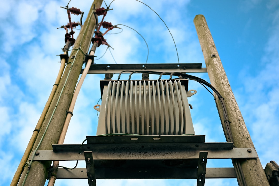
Distribution systems step the voltage down to levels that residential and commercial appliances can handle. A final transformer, often resembling a gray metal can on a utility pole or a green box on lawns, performs the final step-down to 120/240 volts before the electricity enters your electrical panel.
For a step-by-step look at this final leg of the journey, read From Transformer to Plug Exploring the Low Voltage Grid.
Real-Time Balancing: How Operators Maintain Grid Reliability
One of the most mind-boggling aspects of receiving electricity from grid systems is that electricity must be consumed the exact millisecond it is generated. Because large-scale grid storage is historically limited, grid operators—known as balancing authorities—must constantly balance supply and demand in real time.
If demand spikes (for example, on a hot afternoon when millions of air conditioners turn on) and operators do not bring more generation online, the grid’s frequency will drop. If it drops too low, safety systems will automatically disconnect power plants to protect them, potentially triggering a cascading blackout. Conversely, if there is too much supply and not enough demand, the frequency will rise, which can also damage grid infrastructure.
Operators use a mix of “baseload” power plants (which run continuously) and rapid-response “peaker” plants (often natural gas or hydroelectric facilities) to maintain this delicate equilibrium. To see real-world examples of how this operational dance powers our daily lives, check out our article on Shocking Examples How the Electrical Grid Powers Our Lives.
Managing Power Outages and Black Starts
Despite the best efforts of balancing authorities, outages still happen. In the United States, the majority of reliability issues are caused by factors outside the control of grid operators, such as physical distribution or transmission lines downed during extreme weather events.
When a catastrophic blackout occurs and the grid goes completely dark, operators cannot simply flip a switch to turn it back on. Most large power stations require electricity from the grid just to start their own operations (to run pumps, blowers, and control systems).
To recover from a total collapse, operators must execute a highly coordinated “black start.” This involves using small, self-starting generators (like diesel generators or hydroelectric plants) to gradually energize local lines and bring larger power plants back online step-by-step.
To understand this emergency playbook, read The Black Start Blueprint How Power Grids Come Back to Life.
Electricity Markets, Rates, and Consumer Access
How do we actually buy and sell electricity from grid utilities? The financial side of the grid is just as complex as the physical side.
In many regions, electricity is traded on wholesale markets where power generators sell their output to utilities and retail providers. Retail providers then sell that electricity directly to homes and businesses.
To explore how these utility companies operate and structure their consumer services, you can visit National Grid: Natural Gas & Electricity or check regional offerings like Massachusetts Electricity | Home – National Grid .
When you look at your utility bill, the cost is typically split into two main categories:
- Supply Costs: The actual cost of the electricity generated at power plants. You can learn more about how these supply rates are calculated by reviewing Supply Costs | Bills, Meters & Rates | National Grid .
- Delivery Costs: The cost to maintain the physical transmission lines, substations, poles, and meters that bring the power to your door. For a breakdown of delivery charges, see Service Rates | Bills, Meters & Rates | National Grid .
The Cost of Sourcing Electricity from Grid Utilities
For residential customers, utilities typically offer a default option known as “Basic Service” if you do not actively choose a competitive third-party electricity supplier. Under Basic Service, the utility purchases power on your behalf through competitive solicitations and passes the cost directly to you without any markup.
Consumers can often choose between different rate structures:
- Fixed Rates: Your price per kilowatt-hour (kWh) remains constant for a set period (usually 6 to 12 months), protecting you from seasonal price spikes.
- Variable Rates: Your price fluctuates monthly based on wholesale market conditions.
For low-income households, many utilities offer dedicated assistance programs. For instance, eligible customers can qualify for discount rate programs that provide bill credits ranging from 32% to 71% of total charges. You can view an official breakdown of these rate structures and discount programs in the 2025 Summary of Rates for Massachusetts .
The Evolution of the Grid: Smart Tech and Renewables
The grid is undergoing its most significant transformation since the days of Thomas Edison. Traditional grids were centralized and analog; the modern grid is becoming highly digital, interactive, and decentralized.
Two major drivers of this evolution are:
- Distributed Energy Resources (DERs): Technologies like residential rooftop solar panels and local battery storage allow consumers to generate their own power.
- Smart Grids: Utilizing advanced sensors, digital communication systems, and smart meters, modern grids can automatically detect outages, reroute power to isolate faults, and communicate real-time pricing to consumers.
This shift toward decentralized, self-healing networks often relies on localized microgrids. To understand how operators manage these advanced networks, read The Brains Behind the Grid Optimizing Microgrid Operations. For a look at how cutting-edge technologies are securing these transactions, explore Why Your Energy Grid Needs a Blockchain Upgrade.
Furthermore, digital platforms like the GridPulse — Electricity Price API are enabling developers and AI agents to access real-time electricity prices, carbon intensity metrics, and generation mix data across dozens of global grid zones.
Integrating Renewable Energy and AI Workloads
As we transition toward a decarbonized future, integrating variable renewable sources like wind and solar presents a massive engineering challenge. Unlike gas or hydro plants, wind and solar cannot be turned on demand.
At the same time, the grid is facing unprecedented demand growth. AI data centers are projected to double their energy consumption by 2030. Because a single LLM inference query can vary up to 20x in carbon intensity depending on where and when it is run, developers are looking for ways to optimize compute workloads.
Open-source protocols like carbonsteward/grid402 are stepping in to solve this. By providing sub-hourly (5-minute) data on generation mixes, emissions, and spot prices, these tools allow AI agents to automatically schedule heavy computing tasks during hours when clean energy is abundant on the grid.
This integration is vital in states like California, where renewable generation is growing rapidly, as documented in the 2023 Total System Electric Generation report.
Frequently Asked Questions about Grid Electricity
What are the three major interconnections in the United States?
The contiguous United States is divided into three primary independent grid networks:
- The Eastern Interconnection: Covers the area east of the Rocky Mountains and parts of eastern Canada.
- The Western Interconnection: Covers the area from the Rocky Mountains to the West Coast, including western Canada.
- The Electric Reliability Council of Texas (ERCOT): Covers most of the state of Texas. Because ERCOT is largely isolated from the other interconnections, it has limited ability to import power during extreme weather emergencies.
Why does the grid use high voltage for long-distance transmission?
The grid uses high voltage because of basic electrical physics. As electricity travels through a wire, electrical resistance causes some of the energy to turn into heat, resulting in line losses. By using step-up transformers to increase the voltage, the current (amperage) is reduced. Lower current means significantly less heat generation and lower energy loss, allowing power to travel hundreds of miles efficiently.
How do microgrids differ from the main electrical grid?
While the main electrical grid is a massive, centralized network, a microgrid is a localized grid that can operate independently. Microgrids feature their own local generation sources (such as solar arrays, wind turbines, or backup generators) and energy storage.
Most importantly, they have the ability to “island”—meaning they can disconnect from the main grid during an outage and continue supplying power to a local facility, hospital, or neighborhood autonomously. You can learn more about the mechanics behind these systems in Power Up The Engineering Behind Microgrids Explained.
Conclusion
As we look toward the future, the demand for reliable, clean electricity from grid networks will only continue to rise. Transitioning to a decarbonized grid requires not just smart software, but a fundamental upgrade of our physical infrastructure.
That is where we at FDE Hydro™ come in. Our patented, modular precast concrete technology—the French Dam—is revolutionizing how we build and retrofit hydroelectric dams and water control systems. By significantly reducing construction costs and installation times across North America, Brazil, and Europe, we are helping communities rapidly deploy reliable, baseload renewable energy to stabilize local grids.
Modernizing the grid is the defining engineering challenge of our generation. To stay informed on how clean energy and grid technology are evolving, explore our complete library of resources in the Category Power Grid Articles.
by Adaptify Support | Jun 15, 2026 | Power Grid Articles
Why Power Grid Voltage Differs Around the World — And Why It Matters
Power grid voltage — the electrical potential that drives current from generation plants to your home or facility — is not the same everywhere on Earth. In fact, two major standards divide the world:
| Region |
Standard Voltage |
Frequency |
Example Countries |
| North America |
120/240 V |
60 Hz |
USA, Canada, Mexico |
| Europe / Most of World |
220–230 V |
50 Hz |
UK, Germany, Australia, most of Asia & Africa |
| Dual-voltage exceptions |
127 V / 220 V |
60 Hz |
Brazil |
These differences trace back to the late 1800s — the famous rivalry between Thomas Edison and Nikola Tesla — when countries independently locked in their own electrical standards before any international coordination existed.
Today, those early choices still shape every power plant, transformer, and outlet on the planet.
And it’s not just about plug shapes. The voltage and frequency your grid runs at affects:
- Equipment compatibility across borders
- Transmission efficiency over long distances
- Voltage stability as renewable energy sources are added to the grid
- Safety standards for workers and consumers
The U.S. grid alone spans more than 160,000 miles of high-voltage transmission lines, connecting over 7,000 power plants to roughly 145 million customers. Managing voltage reliably across that scale — and doing it as solar, wind, and hydropower reshape the energy mix — is one of the defining engineering challenges of our time.
I’m Bill French, Sr., Founder and CEO of FDE Hydro™, and my decades of experience in heavy civil construction and hydropower infrastructure have given me a front-row seat to how power grid voltage decisions shape the design, cost, and performance of clean energy projects. In the sections ahead, we’ll break down everything you need to know — from global standards to grid stability to what it all means for modern hydropower.
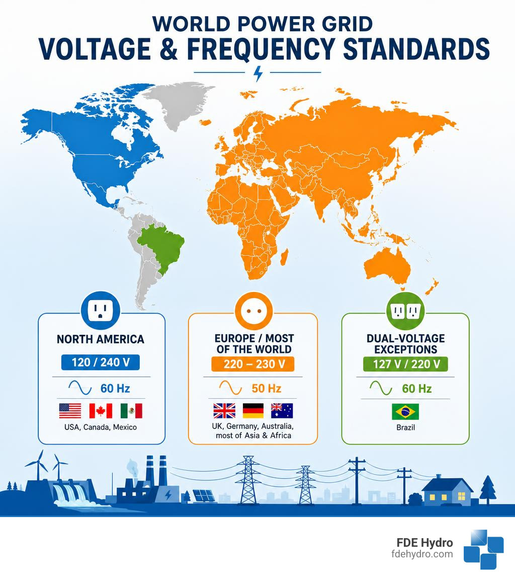
Important power grid voltage terms:
What is Mains Electricity and How is It Delivered?
Mains electricity is the general-purpose alternating current (AC) electric power delivered to homes and businesses. It is the lifeblood of modern society, powering everything from our phone chargers to heavy industrial machinery.
But how does it get to your wall outlet? The process is a highly coordinated journey across multiple layers of infrastructure. To understand this complex dance, it helps to first ask: what does grid mean in electrical engineering? In short, the grid is a massive, interconnected network designed to generate, transmit, and distribute electricity over vast geographic distances.
When you flip a switch, you are drawing on a system that operates in real-time, matching supply with demand instantaneously. To explore this in action, check out these shocking examples of how the electrical grid powers our lives.
The Battle of Currents: Why We Use Alternating Current (AC)
In the late 19th century, the “War of the Currents” pitted Thomas Edison’s Direct Current (DC) against Nikola Tesla and George Westinghouse’s Alternating Current (AC). Edison’s DC systems could only transmit power effectively over a mile or two before the voltage dropped significantly due to line resistance.
Tesla’s AC system won because of a fundamental physical principle: electromagnetic induction. With AC, we can use transformers to easily step up the voltage for long-distance transmission and step it down for safe utilization.
Because transmission line losses are proportional to the square of the current ($I^2R$), raising the voltage allows us to transmit the same amount of power with much lower current, dramatically reducing energy losses over hundreds of miles. To learn more about the basic physics behind this, you can read the Electricity 101 | Department of Energy guide.
Single-Phase vs. Three-Phase Power Delivery
Once the electricity reaches your local area, it is delivered using one of two configurations:
- Single-Phase Power: Typically used for residential and light commercial applications. It delivers a single AC sine wave. In a 60 Hz system, the voltage oscillates back and forth, crossing the “zero-voltage” mark 120 times every second. While this is unnoticeable for lighting and small electronics, it is not ideal for large electric motors.
- Three-Phase Power: Used for industrial facilities, large commercial buildings, and generation plants. It consists of three separate AC sine waves offset by 120 degrees. This means that as one phase drops toward zero, another is peaking. This constant, smooth delivery of power is highly efficient for running large motors, heavy machinery, and industrial water pumps.
Demystifying Power Grid Voltage: Generation, Transmission, and Distribution Layers
To move electricity from a turbine to a toaster, the grid relies on a series of distinct layers, each operating at a specialized power grid voltage.
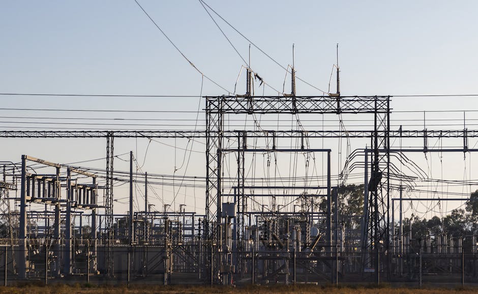
At the generation station, step-up transformers raise the voltage to extreme levels for long-distance travel. Once the electricity nears its destination, step-down transformers lower the voltage to safe, usable levels. You can explore the physical infrastructure behind this in our guide on High Voltage Lines: The Backbone of Our Power Grid.
Voltage Classifications: High, Medium, and Low Voltage
The grid is divided into four distinct operational layers, each classified by its voltage range as outlined in Power System Fundamentals: U.S. Grid Structure, Voltage Levels, and Core Studies | EleCalculator:
- Generation: Power plants (such as hydro, nuclear, or gas) typically generate electricity at medium voltages, usually between 4.16 kV and 34.5 kV. A generator step-up transformer immediately boosts this to transmission levels.
- Transmission (High Voltage): Transmission lines carry bulk power over long distances. In North America, transmission voltages typically range from 69 kV up to 765 kV. Operating at these high levels minimizes thermal losses.
- Subtransmission and Distribution (Medium Voltage): Substations step the voltage down to distribution-primary classes, which commonly range from 4.16 kV to 34.5 kV. This medium voltage travels down street-level lines (either overhead or underground).
- Utilization (Low Voltage): Finally, small distribution transformers (the grey canisters on utility poles) step the voltage down to the final utilization voltage. For residential homes in North America, this is 120/240V split-phase.
For a deeper dive into how these networks are structured structurally, see our breakdown of the various electrical networks and grid expectations.
Nominal, Service, and Utilization Voltages Explained
Engineers categorize voltage into three distinct definitions to ensure equipment functions safely and within standard parameters:
- Nominal System Voltage: The designated value assigned to a circuit or system for the purpose of convenient nomenclature (e.g., 120V, 240V, 480V).
- Service Voltage: The voltage measured at the point where the utility’s system connects to the customer’s electrical installation (the billing meter).
- Utilization Voltage: The voltage measured at the terminals of the operating equipment (the wall outlet or appliance plug).
Because of resistance in building wiring, the utilization voltage is normally slightly lower than the service voltage. National standards, such as the ANSI C84.1-1995 standard, establish strict operating tolerances. These guidelines ensure that utilities maintain service voltages within acceptable limits (typically within $pm 5%$ of nominal) so that end-user equipment is not damaged by overvoltage or starved by undervoltage.
Comparing Global Voltage Standards: Why Regions Differ
The global map of mains electricity is a patchwork of historical compromises. When grids were first constructed in the late 19th and early 20th centuries, there was no global supply chain for household appliances. Consequently, different regions adopted standards based on local engineering preferences and economic conditions.
For a comprehensive breakdown of worldwide electrical standards, you can consult the Voltage, frequency and plug type per country – Royal Brinkman database.
| Country/Region |
Nominal Voltage |
Frequency |
Standard Plug Types |
| United States |
120 V |
60 Hz |
Type A, Type B |
| Canada |
120 V |
60 Hz |
Type A, Type B |
| Europe |
230 V |
50 Hz |
Type C, Type E, Type F, Type G |
| Brazil |
127 V / 220 V |
60 Hz |
Type N |
North American Standards (120V/60Hz)
North America settled on 120V at 60 Hz. This standard relies on a “split-phase” residential delivery system. The utility delivers two 120V hot wires that are 180 degrees out of phase, along with a shared neutral wire.
Standard household outlets connect one hot wire and the neutral to deliver 120V for low-power devices. For heavy appliances like clothes dryers, water heaters, and air conditioners, both hot wires are connected to deliver a full 240V.
In Canada, where more than half of the country’s electricity is generated by massive, highly efficient hydroelectric facilities, the standard remains identical to the U.S. to ensure seamless economic and equipment compatibility. Travelers can find more details about Canadian electrical currents in the Electric plug and socket type in Canada | Adapter or converter? guide.
European and Global Standards (230V/50Hz)
Europe and much of the rest of the world opted for a nominal voltage of 220–230V at a frequency of 50 Hz. The primary advantage of a higher residential voltage is efficiency. Because double the voltage requires half the current to deliver the same amount of power ($P = V times I$), European household wiring can be thinner and experiences lower internal resistive losses.
However, higher voltage carries a greater risk of severe electrical shock, which is why European countries historically developed highly robust safety standards, ground-fault protections, and heavily insulated plug designs.
Brazil represents an interesting dual-voltage hybrid. Depending on the state or municipality, the local grid might supply 127V or 220V, both running at 60 Hz. This split requires travelers and industrial developers to be highly vigilant about checking local ratings. For guidance on navigating this environment, check out the Travel Adaptor for Brazil | Electrical Safety First resource.
Grid Stability: Managing Fluctuations, Regulation, and Modern Challenges
A stable grid is a balanced grid. Both frequency and power grid voltage must be kept within strict tolerances to prevent equipment damage and grid-wide blackouts.
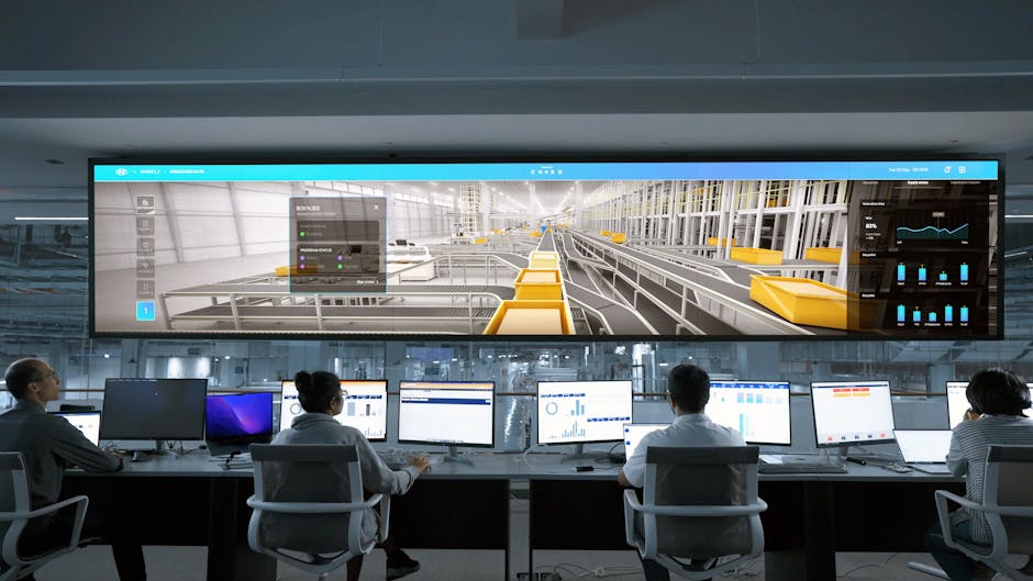
If the grid suffers a catastrophic failure, operators rely on specialized protocols to restore power. You can read about this emergency process in The Black Start Blueprint: How Power Grids Come Back to Life. To maintain normal, day-to-day operations, the grid also relies on a steady foundation of Base Load Power: Understanding the Grid’s Minimum Demand.
How Power Grid Voltage Fluctuations and Overvoltages Affect Equipment
Voltage levels on the grid fluctuate constantly as large loads turn on and off.
- Voltage Sags (Undervoltage): When large industrial motors start up, they draw high inrush currents, causing a temporary dip in local voltage. Severe sags can cause electric motors to overheat, computers to reset, and industrial processes to shut down.
- Transient Overvoltages (Swells and Spikes): Sudden load rejections (such as a factory shutting down) or lightning strikes can cause dramatic voltage spikes. These transients can puncture electrical insulation, destroy sensitive microelectronics, and cause electrical fires.
To combat these issues, utilities use voltage regulation equipment, including load tap changers (LTCs) on substation transformers, line-voltage regulators, and capacitor banks that inject reactive power to boost sagging voltages.
The Impact of Renewable Energy on Power Grid Voltage Stability
The transition to clean energy introduces new complexities to voltage regulation. Traditional power grids rely on massive, spinning synchronous generators (like those in coal, gas, or large hydro plants) that naturally provide physical inertia and automatic voltage regulation.
Modern wind and solar resources, however, are Inverter-Based Resources (IBRs). They interface with the grid through power electronics rather than heavy rotating machinery. This shift creates several challenges:
- Loss of Inertia: With fewer spinning generators online, the grid is more susceptible to rapid frequency and voltage deviations.
- Bidirectional Power Flow: Traditional distribution grids were designed for one-way traffic—from the high-voltage transmission system down to the low-voltage customer. High penetrations of rooftop solar can push power backward up the line, causing localized overvoltages.
- Intermittency: Sudden changes in solar irradiance or wind speed cause rapid power fluctuations, requiring highly dynamic voltage control.
To address these challenges, researchers and grid operators are turning to advanced control strategies. You can read a comprehensive analysis of these emerging issues in the Review of Challenges and Research Opportunities for Voltage Control in Smart Grids (Journal Article) | OSTI.GOV.
Additionally, technologies like smart inverters are being programmed with Volt-Var control capabilities, allowing them to dynamically absorb or inject reactive power to stabilize local voltages. For a deeper look at these techniques, see the Department of Energy’s report on Voltage Optimization.
These challenges are not theoretical. In places like New York, grid operators are facing historically thin safety margins heading into the high-demand summer months, highlighting the urgent need for rapid, reliable grid modernization.
TSO and DSO Coordination in Modern Smart Grids
As distributed energy resources (DERs) like rooftop solar and localized battery storage multiply, the boundary between the Transmission System Operator (TSO) and the Distribution System Operator (DSO) is blurring.
Traditionally, the TSO managed the high-voltage transmission system and bulk generation, while the DSO simply managed the local delivery. Today, voltage stability on the transmission system increasingly depends on the aggregate behavior of millions of small-scale resources connected to the distribution system.
Active coordination is essential. DSOs must monitor and optimize local voltage profiles, while TSOs coordinate wide-area monitoring and control schemes to ensure that local voltage adjustments do not trigger larger, cascading instabilities across the macrogrid.
Frequently Asked Questions about Power Grid Voltage
Why do different countries use different plug shapes and voltages?
Different countries built their electrical grids independently during the late 19th and early 20th centuries. By the time international travel and trade made standardization desirable, the cost of replacing millions of existing outlets, appliances, and transformers was too high. Consequently, countries stuck with their legacy standards, leading to the diverse array of plug shapes and voltages we see today.
What is the difference between service voltage and utilization voltage?
Service voltage is the electrical potential delivered by the utility to your facility’s billing meter. Utilization voltage is the actual voltage available at your wall outlets or equipment terminals. Utilization voltage is typically slightly lower than service voltage due to natural voltage drops caused by resistance in the building’s internal wiring.
Can we harness lightning to power the electrical grid?
No, we cannot. While a single lightning strike contains a massive amount of energy—approximately 1,500 megajoules (MJ), which is enough to power a 100W light bulb for nearly six months—lightning is far too brief, localized, and unpredictable. To equal the output of a standard 1-gigawatt (GW) power plant, we would need to capture and store more than 58,000 perfectly timed lightning strikes every single day. The technology required to safely capture and store such high-voltage, high-current transients in microseconds does not exist.
Conclusion
As we march toward a decarbonized future, grid modernization and voltage stability are more critical than ever. The integration of intermittent wind and solar requires a flexible, resilient grid infrastructure that can adapt to rapid changes in generation and demand.
At FDE Hydro™, we believe that hydropower has a vital role to play in this transition. Beyond producing clean, reliable baseload power, hydroelectric plants act as massive, spinning synchronous condensers that naturally stabilize power grid voltage and frequency.
To accelerate the deployment of these essential grid assets, we developed our patented modular precast concrete technology, known as the French Dam. By replacing slow, carbon-intensive, on-site concrete pouring with precision-engineered, precast modules, we dramatically reduce the construction costs and development timelines of hydroelectric projects and water control structures across North America, Brazil, and Europe.
Whether retrofitting an existing non-powered dam or building a new run-of-river facility, our technology makes clean, grid-stabilizing energy more accessible and cost-effective than ever before.
Are you interested in learning more about the engineering behind modern power systems? Explore our Power Grid Articles to stay informed on the latest trends in grid stability, renewable integration, and clean energy infrastructure.
by Adaptify Support | Jun 8, 2026 | Power Grid Articles
The Layer of the Grid That Powers Almost Everything
The medium voltage grid is the critical middle layer of the electrical power system — sitting between the high-voltage transmission lines that carry electricity across long distances and the low-voltage lines that deliver power to homes and small businesses.
Here’s a quick answer if that’s what you need:
| Question |
Answer |
| What is a medium voltage grid? |
The distribution network segment operating between 1 kV and 36 kV (IEC standard) |
| Where does it fit? |
Between high-voltage transmission and low-voltage end-user supply |
| Who uses it directly? |
Factories, hospitals, airports, water plants, large campuses, and renewable energy farms |
| Why does it matter? |
It carries power to nearly every major load center — and distribution failures cause 92% of all U.S. power outages |
| What’s the U.S. average? |
Around 13 kV, across roughly 5.5 million miles of local distribution lines |
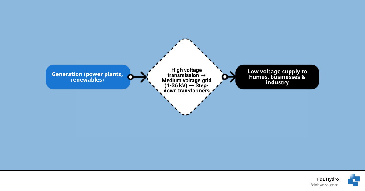
Think of the power system as a river system. High-voltage transmission lines are the wide, fast-moving main river. The medium voltage grid is the network of tributaries branching off to reach communities and industries. Low-voltage lines are the final small streams that reach your front door.
That middle layer — the medium voltage grid — is where most of the action happens. It’s where renewable energy sources connect, where large industrial customers tap in, and where the vast majority of outages originate. Unreliable electricity at this level costs U.S. customers an estimated $85 billion every year.
In 2026, with renewable energy generation expanding rapidly and aging grid infrastructure under growing pressure, understanding how this layer works has never been more important — especially for infrastructure developers and project owners making high-stakes decisions about grid connection and power delivery.
I’m Bill French, Sr., Founder and CEO of FDE Hydro™, and over decades of delivering large-scale civil and energy infrastructure — including run-of-river hydropower facilities that connect directly to the medium voltage grid — I’ve seen how grid architecture shapes project viability and long-term performance. In this guide, I’ll walk you through everything you need to know about how the medium voltage grid works, what’s in it, and where it’s headed.
Medium voltage grid terminology:
What Is a Medium Voltage Grid and Where Does It Sit in the Power System?
A medium voltage grid is the part of the power system that moves electricity from bulk transmission substations toward neighborhoods, commercial districts, industrial sites, community infrastructure, and utility-scale renewable projects. If you want a broader refresher on grid layers, see More on electrical networks.
In practical terms, this is the distribution backbone. It is not the continent-spanning transmission network, and it is not the final low-voltage service line to a house. It is the middle ground that makes both of those layers useful.
How medium voltage is defined
The most widely cited international definition places medium voltage between 1 kV and 36 kV. In practice, utilities may use classes such as 4.16 kV, 12.47 kV, 13.2 kV, 13.8 kV, 15 kV, 24.9 kV, 27 kV, or 34.5 kV depending on local standards and legacy equipment.
Some sources use 1-35 kV and others use 1-36 kV. That difference is mostly about convention rather than physics. The important point is that medium voltage sits well above end-use building voltage and well below transmission-level voltage.
How the medium voltage grid connects transmission to low voltage
Electricity usually follows this chain:
- Generation plant produces power.
- Transformers step voltage up for long-distance transmission.
- Transmission substations step voltage down to medium voltage.
- Medium-voltage feeders carry power through cities, towns, rural service territories, and industrial corridors.
- Local distribution transformers step power down again to low voltage for homes and small businesses.
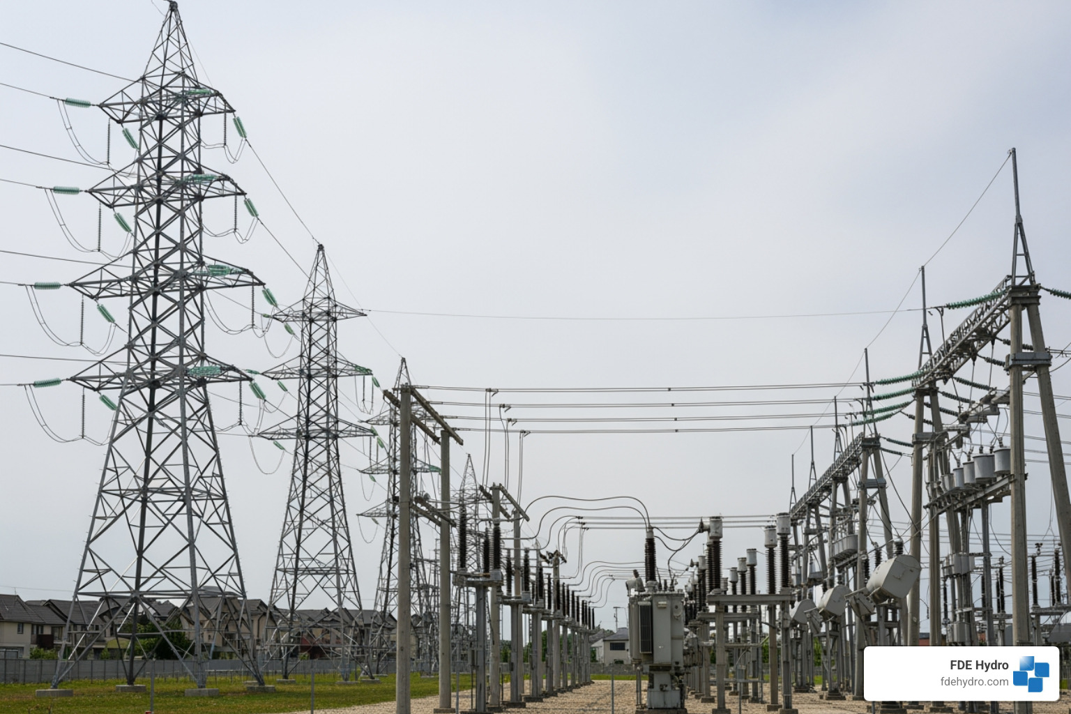
A feeder may leave an HV/MV substation and run for miles overhead in rural areas or underground in dense urban areas. Along the way, it supplies pad-mounted transformers, pole-top transformers, switchgear, and branch circuits.
High vs medium vs low voltage at a glance
| Grid layer |
Typical role |
Typical voltage range |
Best for |
Typical users |
| High voltage |
Bulk transmission |
Above medium voltage classes, often 69 kV and far higher in utility systems |
Long distances with lower losses |
Regional transmission operators, interties, large substations |
| Medium voltage |
Primary distribution |
1 kV to 36 kV |
Moving power across communities and to large loads |
Factories, hospitals, airports, campuses, renewable plants |
| Low voltage |
Final utilization |
Building service and end-use voltage |
Safe end-user delivery |
Homes, small shops, offices |
Why the different layers? Because higher voltage reduces current for the same power transfer, and lower current means lower losses and smaller conductors for long distances. But you would not want transmission voltage showing up at your toaster. Or your coffee maker would become a space program.
Core Components of a Modern Medium Voltage Grid
The medium voltage grid depends on a mix of electrical and control equipment that keeps power flowing safely and reliably. A useful technical overview of one major equipment class is this Medium-voltage switchgear overview.
At the core are substations and feeders:
- HV/MV substations step transmission voltage down to distribution voltage
- Busbars distribute power inside the substation
- Feeders carry medium-voltage power outward
- MV/LV transformer stations step voltage down for final local service
- Sectionalizing points divide networks into controllable segments
Common feeder layouts include:
- Radial feeders: simple and common, especially where cost matters
- Ring networks: offer alternate supply paths and better service continuity
- Looped arrangements with normally open points: a practical compromise between cost and reliability
Transformer stations are often the most visible sign of the medium-voltage system in built-up areas, especially where cables are underground.
Protection, control, and automation equipment
Modern MV networks rely on more than wires and transformers. They also need brains.
Key equipment includes:
- Circuit breakers
- Reclosers
- Ring main units
- Protection relays
- Fault indicators
- Voltage regulators
- Capacitor banks
- SCADA and communications equipment
- Sensors for current, temperature, and line condition
- Cable terminations and joints
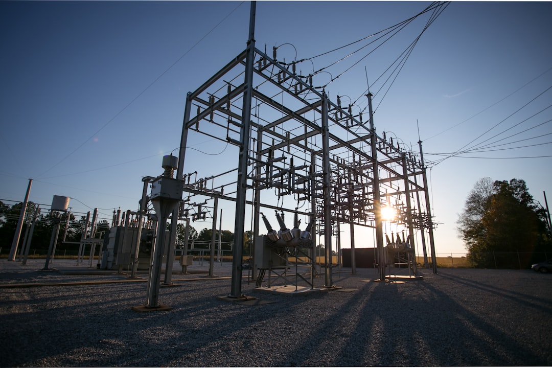
Protection coordination is crucial. If a fault occurs, the utility wants the device closest to the problem to isolate it first, while keeping healthy parts of the feeder energized. That is why relays, breaker settings, and recloser timing matter so much.
Automation adds speed. Utilities increasingly use advanced distribution management systems to support fault location, isolation, and service restoration. A smart feeder can often restore many customers automatically after a fault by switching around the damaged section.
Overhead vs underground medium voltage networks
Both overhead and underground MV systems are common, and each has tradeoffs.
Overhead networks:
- Lower installation cost
- Easier visual inspection
- Faster access for some repairs
- More exposure to storms, wind, ice, and vegetation
Underground networks:
- Better protection from weather and falling trees
- Often preferred in dense urban or visually sensitive areas
- Higher installation cost
- Fault location and repair can be slower and more specialized
In North America, both approaches are used depending on terrain, density, weather risk, and budget. In major cities, undergrounding is common. In rural service territories, overhead feeders remain widespread.
Medium Voltage Grid Applications, Customers, and Renewable Integration
A medium voltage grid does not just serve neighborhoods. It is also the connection point for many of the loads and resources shaping the modern energy system. For related distributed-control thinking, see Microgrid optimization basics.
Typical direct or near-direct MV users include:
- Manufacturing plants
- Hospitals
- Airports
- Universities and large campuses
- Water and wastewater facilities
- Data centers
- Transit systems
- Community microgrids
- Renewable energy projects
- Hydropower facilities
How PV, wind, and hydropower connect to the medium voltage grid
Solar PV plants, wind projects, battery systems, and many small hydro installations often connect at medium voltage through a point of interconnection. The general path looks like this:
- Generation is produced at the plant.
- Inverters or generator step-up transformers raise voltage to an MV class.
- A collector system gathers output from multiple units if needed.
- Protection, metering, and switching equipment interface with the utility feeder or substation.
- Utility studies confirm export limits, fault current impacts, voltage performance, and protection coordination.
For PV and battery projects, inverter behavior matters a lot. For wind and hydropower, generator controls and transformer design also matter. In all cases, the utility wants to know how the plant behaves during faults, voltage fluctuations, and restoration events.
At FDE Hydro, this is especially relevant for run-of-river and water-control infrastructure. Hydropower projects frequently connect at medium voltage because the power level is too large for ordinary low-voltage service but not large enough to justify transmission-class interconnection.
Why medium voltage is used for large loads and community-scale supply
Medium voltage is the sweet spot for customers that need substantial power without building their own transmission network.
Examples include:
- Hospitals that need strong reliability and backup integration
- Airports with extensive lighting, HVAC, and operations loads
- Water plants with large pumps and motors
- Industrial sites with process equipment
- EV charging hubs with major coincident demand
- Campuses that distribute power across multiple buildings
Using MV reduces current compared with low-voltage supply for the same power, which can reduce conductor size and losses across a facility or district.
Power quality impacts from renewable-heavy feeders
As more DERs connect to feeders, power quality becomes more dynamic.
Common issues include:
- Voltage rise during strong solar output
- Flicker from variable generation or motor loads
- Harmonics from inverter-based resources
- Reverse power flow toward upstream substations
- Phase imbalance and voltage asymmetry
- Protection miscoordination if fault current patterns change
Research on asymmetry in renewable-rich MV networks has shown that load conditions can materially change zero-voltage asymmetry, and ignoring load can produce meaningful calculation errors. If you want the technical study, see Research on asymmetry in MV networks with renewables.
The takeaway is simple: renewable integration is not just about adding megawatts. It is also about managing feeder behavior in real time.
Reliability, Safety, and Power Quality Challenges in Medium Voltage Networks
The distribution layer is where customers feel the grid most directly. And it is also where many of the problems live. For a broader everyday perspective, see How grids power daily life.
Why medium voltage grid reliability matters
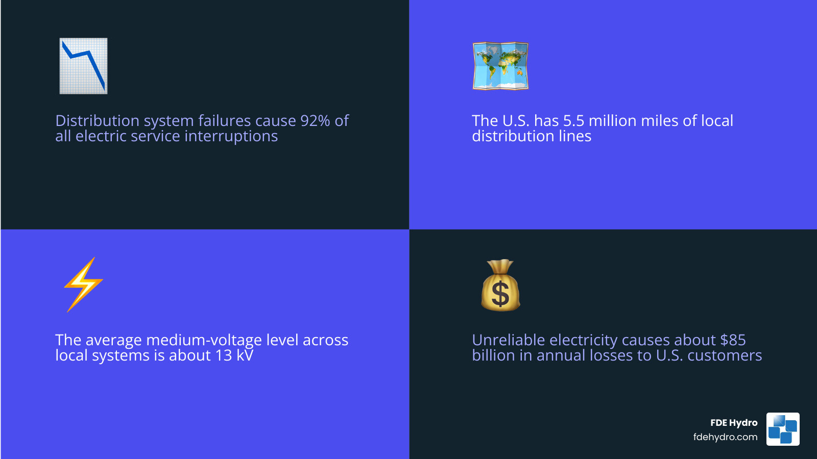
One of the most striking U.S. statistics is that distribution system failures account for 92% of all electric service interruptions. That makes the medium voltage grid a reliability front line, not a side note.
A few more important figures from the research:
- The U.S. has about 5.5 million miles of local distribution lines
- The average medium-voltage level across these local distribution systems is about 13 kV
- Unreliable electricity causes about $85 billion in annual losses to U.S. residential and business customers
Reliability challenges often include:
- Aging poles, cables, and insulation
- Extreme weather
- Vegetation contact
- Animal intrusion
- Equipment overheating
- Feeder congestion from load growth
- Limited visibility on lightly monitored circuits
Restoration time matters too. A short outage at a residence is inconvenient. A short outage at a hospital, water plant, or industrial process can be expensive or dangerous.
Safety issues in medium voltage operations
Medium voltage is not forgiving. Utility crews, contractors, and facility operators treat it with strict procedures for good reason.
Core safety concerns include:
- Arc flash risk
- Induced voltage and backfeed
- Improper switching sequences
- Inadequate grounding and bonding
- Failed insulation
- Public contact hazards after storms
- Step and touch potential near faults
Safe operation depends on:
- Lockout/tagout procedures
- Confirmed de-energization
- Proper earthing and grounding
- Qualified personnel
- Adequate approach distances and clearances
- Tested PPE and insulated tools
- Clear switching plans and communications
This is especially important as DERs increase. A line that looks de-energized from the utility side may still be energized by local generation if interconnection and isolation are not handled correctly.
Power quality problems and how utilities manage them
Power quality issues in MV networks show up as equipment stress, nuisance trips, losses, and customer complaints. Utilities manage them through both planning and active control.
Common medium-voltage faults and disturbances include:
- Single-line-to-ground faults
- Phase-to-phase faults
- Three-phase faults
- Cable insulation breakdown
- Transformer failures
- Broken conductors
- Reclosing misoperations
- Sustained undervoltage or overvoltage
- Harmonic distortion
- Voltage unbalance
Typical mitigation tools include:
- Capacitor banks for reactive support
- Voltage regulators and load tap changers
- Feeder reconfiguration
- Harmonic filtering
- Phase balancing
- Better relay settings
- Power quality monitoring
- Faster fault indicators and line sensors
The more variable the feeder, the more valuable measurement becomes. You cannot fix what you cannot see.
The Future of the Medium Voltage Grid: Smart Grids, Power Electronics, and MVDC
The future medium voltage grid will be more digital, more flexible, and more power-electronics-heavy than the one utilities built decades ago. If you want a conceptual companion piece, see What the grid means in electrical engineering.
How smart grid technologies are upgrading the medium voltage grid
Smart grid upgrades are making MV networks more observable and more controllable.
Important technologies include:
- Line sensors
- Fault passage indicators
- Smart switches and reclosers
- Advanced metering data integration
- SCADA expansion
- ADMS platforms
- Predictive maintenance analytics
- Dynamic line monitoring
- Distributed energy resource management systems
This matters because utilities need real-time visibility into feeder loading, abnormal conditions, and switching status. Research cited in the background also notes that sensor-driven approaches can improve reliability metrics such as SAIDI and reduce outage-related costs by helping utilities spot trouble earlier.
Smart grid modernization also supports DER orchestration, where utilities coordinate solar, batteries, controllable loads, and microgrids rather than treating them as passive attachments.
Cybersecurity belongs in this conversation too. The more connected the field device, the more important secure communications, authentication, patching, and network segmentation become.
The role of medium voltage power electronics
Medium-voltage power electronics are becoming a major enabler of modernization.
Examples include:
- Static VAR support and reactive compensation
- Solid-state transformers
- Back-to-back converters between networks
- Fast voltage support for weak feeders
- Interfaces for batteries and renewables
- Power flow control devices
Wide-bandgap devices such as silicon carbide are especially important because they support higher-efficiency, faster-switching converter designs. Research in this area points to the possibility of direct connection to 15-kV-class grids in some applications without a bulky line-frequency transformer.
That opens the door to more compact and intelligent grid interfaces, though deployment still depends on cost, standards, and utility acceptance.
Where MVDC fits in future distribution architecture
Most medium-voltage networks today are AC. That is still the dominant reality in 2026. But MVDC is getting more attention for niche and emerging applications.
Two useful resources are Medium-voltage direct current explained and Technical overview of MVDC systems.
Potential MVDC use cases include:
- Remote load connections
- Islanded or weak-grid systems
- Renewable collection systems
- Fast charging corridors
- Industrial DC loads
- Interfacing different grid conditions
- Black start support in certain architectures
Research summarized in the source material suggests MVDC can increase transfer capability on some converted assets and may serve projects up to roughly 150 MW in suitable cases. It is promising, but it is not yet the default answer for ordinary distribution planning. Think of it as an important tool in the future toolbox, not a magic wand.
Frequently Asked Questions About the Medium Voltage Grid
What voltage is considered medium voltage?
Most widely, medium voltage is defined as 1 kV to 36 kV under IEC-style classification. In utility practice, many common systems fall in the 4 kV to 35 kV range, with around 13 kV being a familiar U.S. distribution class.
Is the medium voltage grid AC or DC?
Today, the medium voltage grid is overwhelmingly AC. That is the standard form for utility distribution feeders and substations. However, MVDC is emerging for selected applications where power electronics and controllability offer a strong advantage.
Can renewable energy connect directly to medium voltage?
Yes. Solar farms, wind projects, battery storage, and many hydropower facilities commonly interconnect at medium voltage. They typically need inverters or step-up transformers, utility protection review, metering, switching equipment, and interconnection studies covering voltage, fault duty, export limits, and power quality.
Conclusion
The medium voltage grid is the working middle of the electric system. It links transmission to end users, serves major facilities directly, and acts as the main entry point for many renewable resources. It generally operates between 1 kV and 36 kV, often around 13 kV in U.S. distribution practice, and it carries an outsized share of reliability, safety, and modernization challenges.
It is also where the opportunity is.
As utilities expand renewable integration, electrify transportation, harden systems against extreme weather, and digitize operations, medium-voltage networks will keep getting smarter and more dynamic. Better protection, better sensing, stronger automation, and targeted use of power electronics will shape that transition.
For us at FDE Hydro, this matters because energy infrastructure does not stop at the generating asset. Whether we are talking about hydropower, water-control systems, or broader grid-connected renewable development, project success depends on understanding the grid layer that actually delivers and accepts power.
To keep exploring the topic, Browse more power grid articles.
by Adaptify Support | Jun 1, 2026 | Power Grid Articles
What Powers Your Plug? A Plain-English Guide to the Low Voltage Grid
The low voltage grid is the final stage of the electrical power system — the part that delivers electricity directly to your home, office, or factory at a safe, usable voltage.
Quick answer:
| Question |
Answer |
| What is a low voltage grid? |
The segment of the power grid that operates below 1 kV, delivering electricity to end users |
| What voltages does it use? |
100–127 V or 220–240 V AC, at 50 or 60 Hz depending on region |
| Where does it start? |
At the distribution transformer, which steps down medium voltage (5–35 kV) |
| Where does it end? |
At your electricity meter |
| Who uses it? |
Homes, businesses, industrial facilities, public lighting |
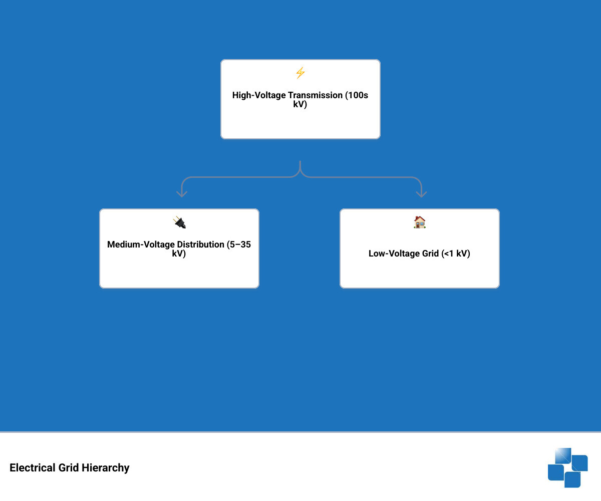
Think of the electrical grid as a long relay race. Power plants generate electricity at very high voltages. That energy travels hundreds of miles on transmission lines, then steps down through substations, and finally reaches your neighborhood through the low voltage grid — the last leg of the race.
It’s easy to overlook this final layer. But it’s arguably the most important one. And as more solar panels, electric vehicles, and smart devices connect to it, the low voltage grid is under more pressure than ever before.
I’m Bill French, Sr., Founder and CEO of FDE Hydro™, and my decades of experience in heavy civil construction and modular hydropower infrastructure have given me a front-row seat to how clean energy generation connects to the low voltage grid and ultimately powers communities. In the sections ahead, we’ll break down exactly how this system works — from transformer to plug.
Handy low voltage grid terms:
What is a Low Voltage Grid?
A low voltage grid is the part of the wider Electrical grid that takes electricity from a local distribution transformer and delivers it to end users at utilization voltage. In plain English, it is the neighborhood-level system that gets power from the pole, pad-mounted transformer, or local kiosk transformer to the meter on a home or business.
Technically, low voltage generally means anything below 1 kV. In practice, the voltages people actually use are much lower:
- 100-127 V in many North American applications
- 220-240 V in much of Europe
- 50 Hz or 60 Hz depending on the regional grid standard
This layer is often called the secondary network because it sits on the secondary side of the distribution transformer. Medium-voltage distribution, typically around 5-35 kV, feeds the transformer. The transformer steps that power down to a safer and more usable level. From there, the low voltage network takes over.
That handoff matters. The transformer is the bridge between the broader utility system and everyday consumption points like:
- houses
- apartments
- offices
- shops
- public lighting
- light industrial facilities
If you want a broader primer on what we mean by “grid” in electrical engineering, our article on What grid means in electrical engineering is a useful companion.
One helpful way to picture the path is this:
- Generation creates electricity.
- Transmission moves it long distances at high voltage.
- Substations reduce it to medium voltage.
- Distribution transformers reduce it again to low voltage.
- The low voltage grid carries it to the meter.
- The customer installation carries it from the meter to outlets, lights, motors, and equipment.
So where does the low voltage grid end? In most definitions, it ends at the electricity meter. Beyond that point, the internal wiring belongs to the customer side of the installation.
Regional Architectures: North America vs. Europe
The overall purpose of the low voltage grid is the same in the United States, Canada, Brazil, and Europe: safe final delivery of electricity. But the physical design can look very different depending on the local voltage standard and network tradition.
One of the biggest differences is service voltage. North America commonly uses 120/240 V systems for residential customers, while much of Europe uses 230/400 V. Because higher voltage can deliver the same power with less current, European low-voltage feeders can usually be longer before voltage drop becomes a problem.
Research consistently shows this difference in architecture:
- North American secondary connections are often limited to about 250 feet, or roughly 80 m
- European low-voltage designs can extend as far as about 1 mile, or roughly 1,600 m
- European distribution transformers are often in the 300-1000 kVA range
- North American neighborhood transformers are commonly smaller, around 25-50 kVA
Here is a simple comparison based on the Low-voltage network reference and standard utility practice:
| Feature |
North America |
Europe |
| Common residential voltage |
120/240 V |
230/400 V |
| Frequency |
60 Hz |
50 Hz |
| Typical LV feeder length |
Up to about 80 m |
Up to about 1,600 m |
| Typical transformer size |
25-50 kVA common in local service |
300-1000 kVA common |
| Typical layout |
More transformers closer to loads |
Fewer, larger transformers serving wider areas |
| Voltage tolerance reference |
ANSI C84.1 often cited |
National and EN-based frameworks |
In North America, lower utilization voltage means utilities usually place transformers closer to customers. In Europe, higher service voltage allows broader low-voltage coverage from each transformer. Brazil often follows 60 Hz systems and uses regional low-voltage arrangements that can resemble either compact urban or more extended distribution models depending on the utility and density.
Voltage tolerance is another important design point. In the United States, ANSI C84.1 is often used as a reference, with service voltage targets that keep delivered power within an acceptable band. If voltage drifts too low, motors struggle and electronics may misbehave. Too high, and equipment stress rises. The grid’s job is not just to deliver power, but to deliver good power.
Earthing also differs by region. Utilities may use TN, TT, or related earthing arrangements depending on local codes and practices. The details vary, but the goal is always the same: provide a controlled fault path and reduce shock risk.
Topologies and Components of the low voltage grid
Not all low-voltage systems are built the same way. Utilities choose topology based on reliability needs, load density, cost, and geography.
The three classic low-voltage network topologies are:
- radial networks
- spot networks
- grid networks
Radial networks
A radial network is the simplest and most common arrangement. Power flows along one main path from the transformer to customers. If a fault occurs on that path, customers downstream can lose service until the issue is isolated and repaired.
Radial systems are popular because they are:
- less expensive to build
- easier to protect
- simpler to operate
- well suited to suburban and rural areas
In lower-density service territories, a single feeder may serve many customers, and a rural primary feeder may supply dozens of distribution transformers. Radial design is the workhorse of the power world. It is not glamorous, but neither is a wrench, and both are essential.
Spot networks
Spot networks are used where reliability matters much more than lowest cost. They usually serve one concentrated site through multiple transformers connected in parallel on the low-voltage side.
Typical applications include:
- hospitals
- large commercial buildings
- business districts
- critical public facilities
These systems often use network protectors. A network protector is a specialized breaker that prevents reverse power flow from the low-voltage side back into a failed transformer or feeder. That way, a problem upstream does not drag the whole site down with it.
Grid networks
Grid networks are even more interconnected. They are common in dense downtown areas where multiple low-voltage feeders and transformers are tied together through underground conductors. Customers may be served from several paths at once, which greatly improves continuity of service.
Benefits include:
- high redundancy
- fewer outages from single equipment failures
- better service continuity for dense urban loads
Protection in these systems is more sophisticated. Utilities may use:
- network protectors
- cable limiters for fast short-circuit isolation
- coordinated protective devices across multiple feeders
Grid networks are more complex and more expensive, but for central business districts and other critical load centers, the reliability benefit can be worth it.
For a more general look at how grid designs affect daily life, see our article on how the electrical grid powers our lives.
Key Components of the low voltage grid
Whatever the topology, most low-voltage networks are built from a familiar set of parts.
These are the entry point to the low-voltage system. They step power down from medium voltage, often 5-35 kV, to end-user voltage. They can be:
- pole-mounted
- pad-mounted
- installed in kiosks or compact substations
- placed in vaults in dense urban areas
Feeders
Low-voltage feeders carry power from the transformer into the neighborhood or local service area. They may be overhead or underground. Feeder size is selected based on expected load, voltage drop limits, fault duty, and future growth.
Service drops or service lines
These are the final conductors from the low-voltage feeder to the individual customer connection point and meter. In overhead systems, this may be a visible drop to a house. In underground systems, it may be a buried service lateral.
Protection devices
Safety and reliability depend on layered protection, including:
- fuses
- circuit breakers
- residual current devices in consumer installations
- network protectors in spot and grid networks
- cable limiters in interconnected urban systems
Smart meters
The traditional meter simply measured energy use. The modern smart meter does much more. It can support interval data, outage detection, remote reading, and in some cases better visibility into the low-voltage system itself.
That matters because the low-voltage layer has historically been the least visible part of the distribution system, even though it can be far larger than the medium- and high-voltage layers combined. Some utility analyses suggest the LV network can be 10 times the size of the upper distribution network.
If you are interested in how distributed assets and local control fit into this picture, our Microgrid Technology guide is a good next step.
Modern Challenges and Digitalization
For decades, many utilities treated the low voltage grid as mostly passive. Power went one way, from transformer to customer, and loads were fairly predictable. That world is fading fast.
Today, the LV network is where the energy transition becomes very real. The main pressures include:
- rooftop solar PV exporting back to the grid
- EV charging creating sharp evening peaks
- heat pumps increasing winter demand in electrified buildings
- batteries changing charging and discharge patterns
- rising expectations for resilience and power quality
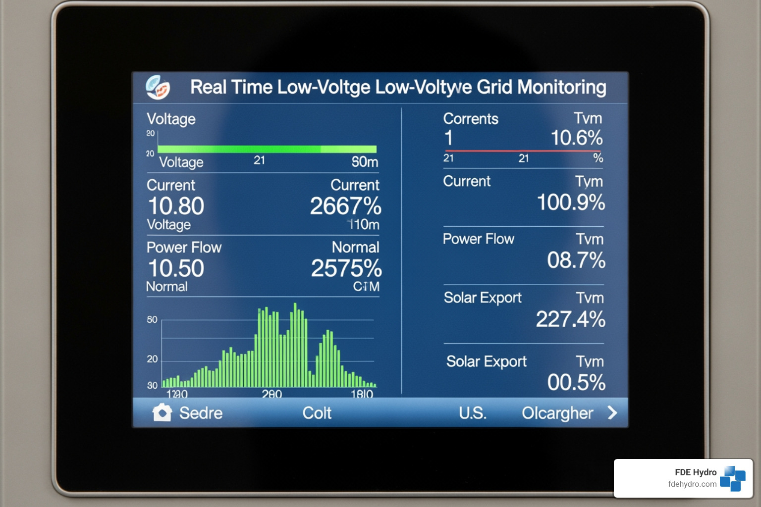
This creates two opposite operating extremes:
-
Low load, high generation
In sunny periods, rooftop solar can push voltage upward and even reverse normal power flow.
-
High load, low generation
During peak charging or heating periods, feeders and transformers can become overloaded and voltage can sag.
These issues are one reason utilities now talk about the LV network as the “final frontier” of grid orchestration. It is big, complex, and historically under-instrumented.
Digitalization is changing that. Smart meters, sensors, and software platforms are improving visibility and enabling more active control. Worldwide smart meter adoption is projected to reach about 78% by 2028, which is a major shift for low-voltage data availability.
A modern low-voltage management stack may include:
- AMI and smart meter data
- transformer-level monitoring
- dynamic topology models
- low-voltage state estimation
- outage analytics
- voltage quality monitoring
- DER visibility and control
This trend also matters for regions where FDE Hydro works, including the United States, Canada, Brazil, and Europe. As more renewable generation comes online, local distribution constraints increasingly shape what projects can connect, how fast they can connect, and how reliably they can operate.
Optimizing the low voltage grid with Smart Technology
The good news is that utilities are not flying blind anymore. Research on modern low-voltage optimization shows real gains from coordinated control strategies.
Some standout findings include:
- coordinated voltage control can reduce voltage violations by up to 20%
- integrated voltage-reactive power control can cut imbalance by about 25%
- optimal tap control can increase PV hosting capacity by up to 67%
- short-term solar forecasting can reduce unnecessary tap changer operations by nearly 56%
How does that work in practice?
Voltage control
Voltage must stay within acceptable limits at the customer service point. Utilities can manage this through transformer tap settings, feeder design, reactive power support, and smarter DER control.
Tap changers
On-load tap changers and voltage regulators adjust transformer output to keep voltage stable as demand and generation change. In a DER-heavy network, those adjustments can become more frequent, which is why smarter forecasting matters.
Forecasting and analytics
Short-term solar forecasting helps utilities avoid overreacting to passing clouds and sudden output swings. Better forecasting means fewer unnecessary mechanical operations and longer equipment life.
Flexible demand
Smart EV charging, demand response, and coordinated heat pump operation can shift or smooth load. Instead of reinforcing every feeder immediately, utilities can sometimes buy time with intelligence.
LVDC trends
Low-voltage DC, or LVDC, is an emerging topic worth watching. Traditional low-voltage systems are usually AC, but DC networks can make sense in selected applications where loads or generation are already DC-based, such as:
- battery systems
- EV charging hubs
- data-rich commercial buildings with power electronics
- certain microgrids and hybrid systems
DC can reduce some conversion losses and simplify integration with batteries and solar. That said, AC remains the standard for public low-voltage distribution, and LVDC is still a niche rather than a replacement.
If you want to dig deeper into intelligent control, our article on optimizing microgrid operations explores many of the same digital ideas at the local grid scale.
Frequently Asked Questions about Low Voltage Networks
What is the difference between a low voltage grid and a microgrid?
A low voltage grid is usually part of the public utility distribution system. A microgrid is a smaller local power system that can often operate either connected to the main grid or independently.
Key differences:
- The low voltage grid is a voltage layer in the wider utility network.
- A microgrid is an operational system with local generation, controls, and defined boundaries.
- A microgrid can often island, meaning it can disconnect and keep serving local loads on its own.
- A standard low-voltage feeder usually cannot do that by itself.
In other words, “low voltage” describes the electrical level, while “microgrid” describes the architecture and operating mode. Many microgrids operate at low voltage, but not every low-voltage network is a microgrid.
For a full primer, see What Is A Microgrid.
How do utilities ensure safety in LV networks?
Safety starts with design and continues through protection, grounding, and maintenance.
Core safety measures include:
- earthing systems that create a controlled fault path
- fuses and circuit breakers that interrupt dangerous current
- residual current devices that detect leakage current
- insulation and enclosure standards
- voltage control within acceptable limits
- clear separation between utility and customer installations
Touch voltage matters too. Around 50 V is often treated as an approximate safety threshold for dangerous contact conditions, which is one reason low voltage still requires serious protection even though it is far below transmission levels.
In more complex spot and grid networks, utilities also rely on:
- network protectors to block harmful reverse flow
- cable limiters for rapid short-circuit isolation
- coordinated protection settings so only the faulted section trips
As low-voltage systems become more dynamic, safety increasingly depends on visibility as well as hardware. Better data helps utilities identify overloads, outages, and abnormal voltage conditions earlier.
Why is the low voltage grid called the “final frontier” of the energy transition?
Because this is where decentralization shows up first and most intensely.
The low-voltage layer is where:
- prosumers export rooftop solar
- EVs plug in after work
- homes electrify heating
- batteries charge and discharge
- customer expectations for reliability become very personal
Historically, this layer was not heavily monitored. Utilities understood the transmission system well, the substation fairly well, the medium-voltage feeders reasonably well, and the low-voltage layer… less well. That has changed because the edge of the grid is now active, not passive.
Data-driven analytics, smart meters, and local controls are helping utilities move from guesswork to informed orchestration. That shift is essential for resilience, flexibility, and faster integration of clean energy resources.
And when the grid does suffer major disturbances, restoration still depends on understanding how all layers reconnect safely. Our article on how power grids come back to life adds useful context to that bigger picture.
Conclusion
The low voltage grid may be the last step in the power system, but it is no small detail. It is the layer that turns bulk electricity into usable energy at homes, businesses, industrial sites, and public infrastructure.
It also happens to be where many of the most important grid changes are happening right now:
- more distributed solar
- more electrified transport
- more electric heating
- more smart devices
- more need for visibility and control
At FDE Hydro, we care about this end of the system because generation and delivery are inseparable. Our work in modular hydropower and water-control infrastructure supports a cleaner, more flexible power future, but that future only succeeds if the electricity can be absorbed and managed all the way down to the local distribution edge.
Hydropower remains one of the grid’s most valuable balancing resources, especially when paired with modern digital control and strong distribution planning. If you want to explore that connection further, read 4 Reasons Why Hydropower Is The Guardian Of The Grid.
And if you would like more plain-English guides on transmission, distribution, resilience, and restoration, visit our power grid article library.
by Adaptify Support | May 25, 2026 | Power Grid Articles
What Is the High Voltage Grid — and Why Does It Matter?
The high voltage grid is the backbone of modern electricity supply — a vast network of transmission lines, substations, and transformers that moves bulk power from where it is generated to where it is needed.
Quick answer for those in a hurry:
| Question |
Answer |
| What is the high voltage grid? |
A network that transmits bulk electricity at voltages of 110 kV and above from power plants to local substations |
| Why use high voltage? |
Higher voltage means lower current, which dramatically reduces energy lost to heat over long distances |
| AC or DC? |
Mostly AC; HVDC is used for very long distances and undersea cables |
| Who manages it? |
Transmission System Operators (TSOs) and Regional Transmission Organizations (RTOs) |
| How efficient is it? |
US transmission losses have dropped from 6.6% in 1997 to around 5% by 2019 |
Every time you flip a switch, electricity has already traveled hundreds of miles through this system — often invisibly, silently, and at voltages that would be unrecognizable to the average household. Your home runs on roughly 230 volts. The lines outside your city carry up to 765,000 volts or more.
That gap is not an accident. It is engineering by design — and understanding it matters more than ever as grids strain under the weight of data centers, electrification, and the clean energy transition.
Consider Grand Coulee Dam: its 6,809 MW of generating capacity moves out through just six 500 kV transmission circuits. That single example captures the scale and precision the high voltage grid demands.
I’m Bill French, Sr., Founder and CEO of FDE Hydro™ — and for decades, my work in heavy civil construction and hydropower innovation has placed me squarely at the intersection of energy generation and the high voltage grid that delivers it. That experience shapes everything in this guide.
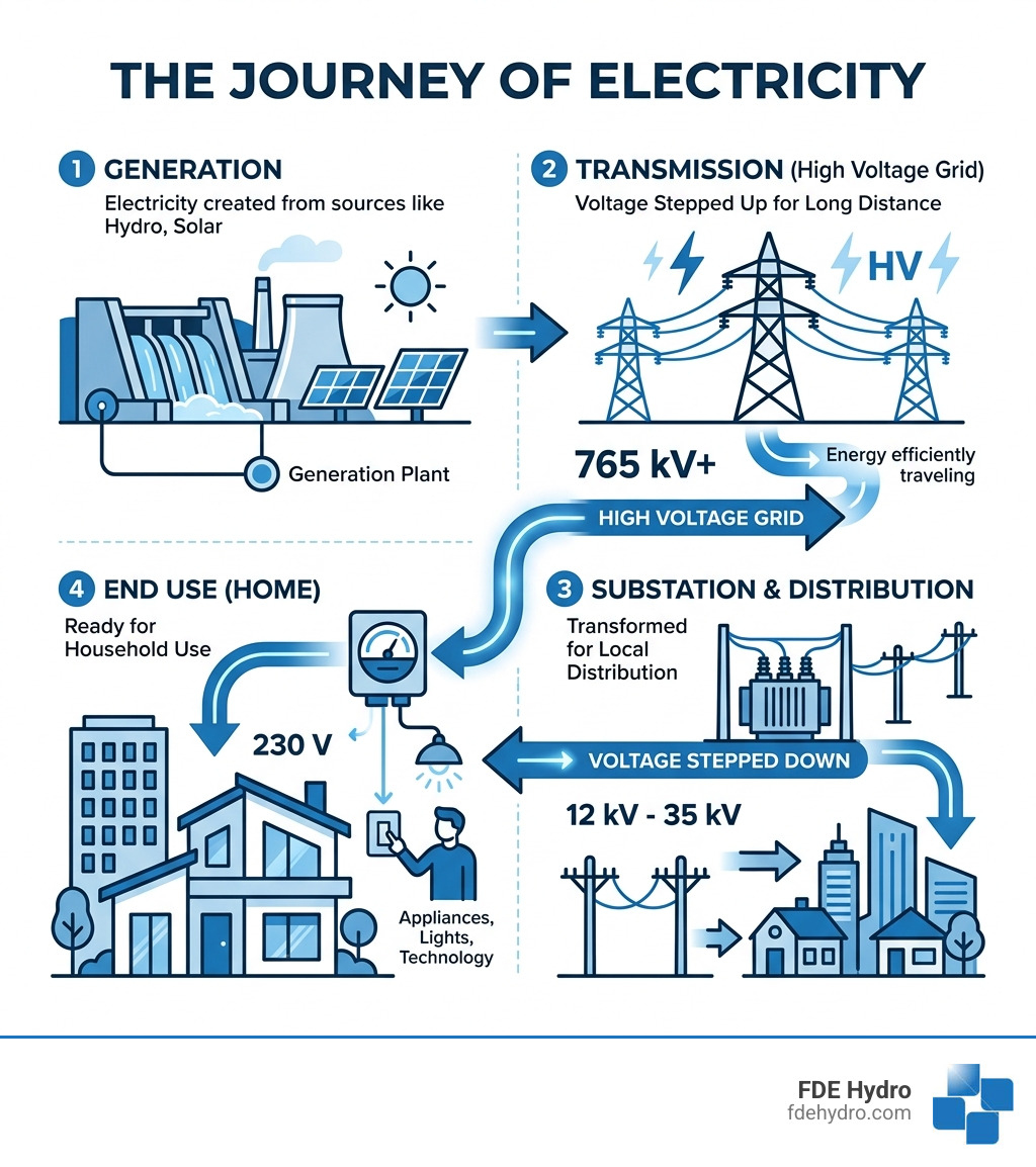
High voltage grid vocab explained:
Understanding the High Voltage Grid: Transmission vs. Distribution
When we talk about the power grid, it’s easy to picture it as one giant web of wires. However, it is actually divided into two distinct stages: transmission and distribution. Unplugging the mystery of the grid helps us see that these aren’t just different names for the same thing—they serve entirely different purposes.
Electric power transmission is the “bulk movement” of energy. Think of it as the interstate highway system for electricity. It carries massive amounts of power from generating sites, like large hydroelectric dams or wind farms, over long distances to electrical substations. These lines are built to handle extreme pressure. According to TenneT grid operations, transmission-level voltages are usually considered to be 110 kV (110,000 volts) and above. In the United States, common levels range from 230 kV to 500 kV.
Once that electricity reaches a local substation, it enters the distribution phase. This is the local street network. Here, step-down transformers reduce the voltage to levels safe for residential and commercial use—typically 230V or 400V. While distribution gets the power to your front door, the high voltage grid is what does the heavy lifting to get it across the country.
The Physics of Efficiency: Why High Voltages Reduce Energy Loss
You might wonder: why bother cranking the voltage up so high just to step it down later? The answer lies in the physics of efficiency.
When electricity travels through a wire, it meets resistance. This resistance turns some of the electrical energy into heat—a phenomenon known as Joule heating or $I^2R$ losses. The “I” stands for current, and the “R” stands for resistance. Because the loss is proportional to the square of the current, even a small reduction in current leads to a massive reduction in energy waste.
By increasing the voltage, we can transmit the same amount of power with much less current. It’s like increasing the pressure in a water pipe to move more water through a thinner hose.
Statistics of Scale
The impact of this efficiency is staggering. Electric power transmission fundamentals show that a 100-mile span at 765 kV carrying 1,000 MW of power might lose only 0.5% to 1.1% of its energy. In contrast, a 345 kV line carrying that same load across the same distance would lose about 4.2%.
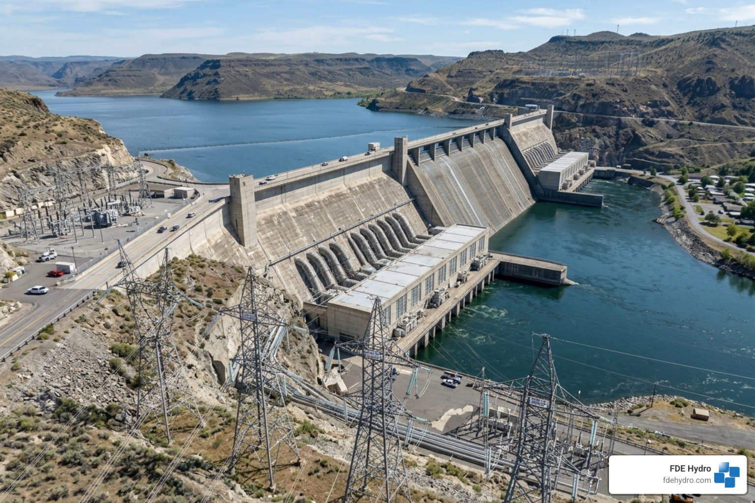
To minimize these losses further, engineers use:
- Bundle Conductors: Using multiple cables for a single phase to reduce “corona discharge” (the hissing sound you sometimes hear near big lines).
- Kelvin’s Law: An economic principle used to find the “sweet spot” between the cost of thicker, more expensive wires and the cost of energy lost to resistance.
In the US, these strategies have paid off. Transmission and distribution losses were estimated at 6.6% in 1997, but improved grid management brought that down to a steady 5% between 2013 and 2019.
AC vs. DC: Comparing Current Types in Modern Transmission
For over a century, the “War of the Currents” between Thomas Edison (DC) and Nikola Tesla (AC) has shaped our world. Alternating Current (AC) won the early battle because it could be easily stepped up or down using transformers, making it the standard for the high voltage grid.
However, High-Voltage Direct Current (HVDC) has made a massive comeback in the 21st century. While AC is great for regional networks, HVDC is the champion of long-distance and specialized applications.
| Feature |
Alternating Current (AC) |
Direct Current (DC) |
| Best For |
Regional grids & local distribution |
Ultra-long distances & subsea cables |
| Distance Limit |
Effective up to ~4,000 km |
Effective up to ~7,000 km |
| Subsea Use |
Limited by capacitance (>50km) |
Excellent for long undersea links |
| Grid Linking |
Requires synchronized frequency |
Can link unsynchronized grids |
A prime example is the HVDC Itaipu project in Brazil, which moves massive amounts of hydropower over 800 km. Another modern marvel is the Viking Link, the longest land-and-subsea interconnector in the world, stretching 765 km between the UK and Denmark. HVDC is also essential for connecting grids that aren’t in sync, acting as a “firewall” that prevents a blackout in one region from cascading into another.
Managing Stability within the High Voltage Grid
Keeping the grid stable is a balancing act that happens every millisecond. The Brains Behind The Grid are the Transmission System Operators (TSOs). They must ensure that the supply of electricity exactly matches the demand.
In Europe, the grid frequency is maintained at 50 Hz, while in North America (including New York, California, and Canada), it is 60 Hz. If the frequency deviates too far because of an imbalance, equipment can be damaged, or the grid can collapse. TSOs use “reactive power” support—like capacitor banks and FACTS (Flexible AC Transmission Systems) devices—to stabilize voltage and keep the power flowing smoothly.
Infrastructure and Components: Overhead Lines vs. Underground Cables
If you look up, you’ll see the most common component of the high voltage grid: overhead lines. These are usually made of aluminum alloy, often reinforced with steel (ACSR). They aren’t insulated with rubber like the wires in your walls; instead, they use the air itself as an insulator, which is why they are hung high up on lattice steel pylons.
Overhead vs. Underground: The Great Debate
We are often asked: “Why don’t we just put everything underground?” It’s a fair question, especially in storm-prone areas of Kansas or crowded cities like New York City.
Overhead Lines:
- Pros: Much cheaper to build (US$128.9 billion was spent on T&D equipment globally in 2011 alone); easier to find and fix faults; cooled by the wind.
- Cons: Vulnerable to weather (wind speeds as low as 23 knots can cause issues); visual impact; requires large clearings.
Underground Cables:
- Pros: Hidden from view; protected from wind and ice; takes up less surface space in urban areas.
- Cons: Costs up to 10 times more than overhead lines; harder to repair; limited by “capacitance” in AC systems, which restricts how far they can carry power before losing it.
The North American power transmission grid relies heavily on overhead lines for its massive “backbone” because the sheer scale of the continent makes undergrounding cost-prohibitive for long-haul transmission.
Grid Management, Economics, and Security Challenges
The high voltage grid is a market as much as it is a machine. Long-distance transmission costs roughly US$0.005–0.02 per kWh. When you compare that to retail rates that can exceed $0.10 per kWh, it’s clear that transmission is a relatively small but vital part of your bill.
However, the grid is currently at a crossroads. We are seeing a massive surge in demand driven by:
- Data Centers: A single large data center can consume as much power as 80,000 homes.
- AI Expansion: AI and grid expansion are forcing utilities to build new lines faster than ever, often facing pushback from landowners.
- Electrification: The shift toward EVs and electric heating is changing when and where we need power.
Security and Future Tech for the High Voltage Grid
Modern grids face more than just weather threats. Cybersecurity is a top priority as hackers target the digital controls that manage power flow. Physical security is also a concern, as transmission towers are often located in remote, difficult-to-monitor areas.
To meet these challenges, the industry is looking toward Ultra High Voltage (UHV) development. China has already pioneered 1,100 kV DC systems that can move power across entire continents.
Other innovations include:
- Reconductoring: Replacing old wires with high-tech materials that can carry twice the power without needing new towers.
- Superconducting Cables: Wires cooled to extreme temperatures that have zero electrical resistance.
- Grid-Enhancing Technologies (GETs): Using sensors for “dynamic line ratings,” which allow operators to push more power through lines when the weather is cool and windy.
If the grid fails entirely, we rely on the Black Start Blueprint—a carefully choreographed plan to restart the grid using “firm” power sources like hydropower.
Frequently Asked Questions about High Voltage Transmission
Are there health risks associated with living near high-voltage lines?
This is a common concern. However, scientific evidence from decades of study has not established a direct link between the electromagnetic fields (EMF) from power lines and long-term health issues. Most countries follow international safety standards that require specific “setback” distances to ensure that EMF levels at ground level are well within safe limits.
Why don’t we put all high-voltage lines underground?
As mentioned, it’s mostly about economics and physics. Undergrounding costs about 10 times more than overhead lines. Furthermore, underground AC cables act like giant capacitors, which creates “phantom” power loads that make long-distance transmission nearly impossible without expensive compensation equipment.
What is the difference between High Voltage (HV) and Extra High Voltage (EHV)?
In the industry, we generally classify voltages as:
- High Voltage (HV): 110 kV to 230 kV. These are the workhorses of regional transmission.
- Extra High Voltage (EHV): 345 kV to 765 kV. These are used for moving massive amounts of power over hundreds of miles.
- Ultra High Voltage (UHV): Above 800 kV (DC) or 1,000 kV (AC), used for intercontinental “supergrids.”
Conclusion
The high voltage grid is the silent engine of our modern life. As we move toward a future powered by clean energy, the importance of this infrastructure will only grow. At FDE Hydro™, we understand that a reliable grid starts with reliable generation.
Our innovative, patented modular precast concrete technology—the “French Dam”—is designed to make building and retrofitting hydroelectric dams faster and more cost-effective. By providing “firm” power that can balance out intermittent wind and solar, hydropower remains one of the 4 Reasons Why Hydropower Is The Guardian Of The Grid.
Whether it’s in the United States, Canada, Brazil, or Europe, we are committed to strengthening the energy backbone that keeps our world running.
Ready to dive deeper into energy? Explore more power grid articles to learn how we’re building the future of sustainable power, one dam at a time.
by Adaptify Support | May 20, 2026 | Power Grid Articles
The types of electrical grid that power our modern world are more varied — and more fascinating — than most people realize. From continent-spanning synchronous networks to small, self-sufficient local systems, each grid type plays a distinct role in how electricity gets from a generator to your outlet.
Here is a quick overview of the main types:
| Grid Type |
Scale |
Key Characteristic |
| Wide Area Synchronous Grid |
Regional / Continental |
Generators synchronized at same AC frequency |
| Super Grid |
Multi-national |
HVDC lines move huge amounts of power over vast distances |
| Microgrid |
Local / Community |
Can “island” and run independently from the main grid |
| Isolated Grid |
Remote / Off-grid |
No connection to a larger network |
| Centralized Grid |
National |
Power flows one-way from large plants to consumers |
| Smart Grid |
Any scale |
Two-way digital communication and automation |
| Distributed Grid |
Local / Regional |
Power generated close to where it is used |
Engineers often call the U.S. grid the biggest machine ever built — and they are not wrong. It links over one million megawatts of generating capacity across roughly 600,000 miles of transmission lines and 5.5 million miles of distribution lines. The story of how that machine grew, split into different forms, and is now evolving again is worth understanding — especially if you work with large-scale energy infrastructure.
Every grid, regardless of type, shares the same basic flow:
- Generation — Power is produced at a plant (coal, gas, nuclear, hydro, wind, solar)
- Transmission — High-voltage lines carry bulk electricity over long distances
- Distribution — Voltage is stepped down and delivered to neighborhoods and buildings
- Load — End users consume the electricity
What differs between grid types is how that flow is organized, how far it travels, who controls it, and how resilient it is when something goes wrong.
I’m Bill French Sr., Founder and CEO of FDE Hydro™, and over five decades in heavy civil construction — including hydropower development — I’ve seen how the types of electrical grid shape the decisions made around water infrastructure and energy delivery. That experience is what grounds everything you’ll read in this guide.
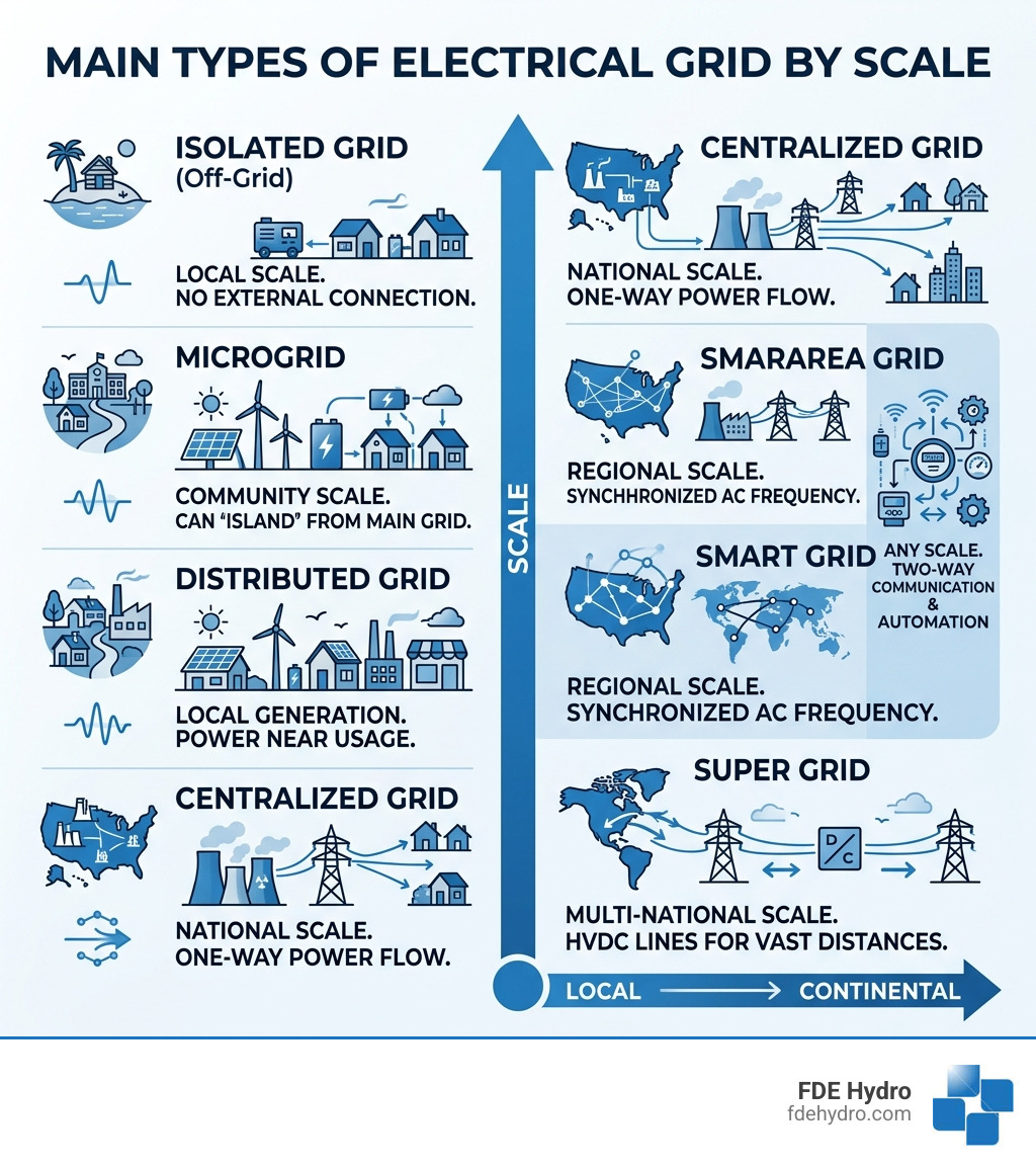
Types of electrical grid terms simplified:
Categorizing the Main Types of Electrical Grid by Scale
When we talk about an electrical grid, we aren’t just talking about wires on a pole. We are talking about a complex hierarchy of systems. The scale of a grid determines its operational independence—essentially, how much it relies on its neighbors to keep the lights on.
In North America and Europe, we primarily deal with massive interconnected systems, but as we move toward 2026, smaller, localized grids are becoming just as vital for resilience.
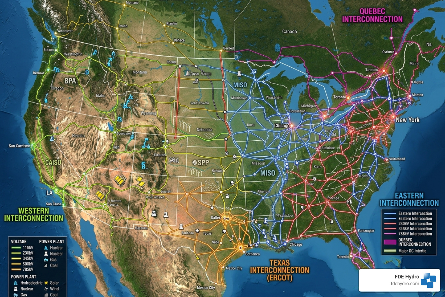
Wide Area Synchronous Grids: The Continental Giants
A wide area synchronous grid is the heavyweight champion of the energy world. These are regional or continental-scale networks where all connected generators operate at the exact same AC frequency. This synchronization is crucial; if one generator falls out of step, it can cause physical damage to equipment or trigger a cascading failure.
In our neck of the woods, the North American power transmission grid is divided into five main interconnections:
- The Eastern Interconnection: Covering the area east of the Rockies (excluding most of Texas and Quebec).
- The Western Interconnection: Covering the area from the Rockies to the Pacific Coast.
- The Texas Interconnection (ERCOT): Operating mostly independently within the state of Texas.
- The Quebec Interconnection: A distinct grid in Canada, known for its massive hydropower exports.
- The Alaska Interconnection: Which actually consists of several isolated grids rather than one giant loop.
One of the most interesting technical quirks is the frequency. North American interconnections operate at a nominal 60 Hz, while European grids operate at 50 Hz. This difference is a legacy of the early “War of Currents,” but it means that equipment from one continent often can’t be used on the other without significant conversion.
Super Grids: The Future of Global Energy Trade
As we look toward the future of the types of electrical grid, the “Super Grid” is the next logical step. These are wide-area transmission networks designed to trade high volumes of electricity across massive distances—think moving solar power from the Sahara to Northern Europe or hydropower from Northern Canada down to New York City.
The secret sauce for Super Grids is High-Voltage Direct Current (HVDC) technology. While AC is great for local distribution, it loses energy over long distances. Modern HVDC lines can transmit energy with losses of only 1.6% per 1000 km. This efficiency allows us to “smooth out” renewable energy. If the wind isn’t blowing in Kansas, a Super Grid can pull power from a hydroelectric dam in Quebec or a solar farm in California in real-time.
The European Union has even set targets for an Electricity Interconnection Level (EIL) of 15% by 2030, ensuring that national grids can share enough power to keep the entire continent stable.
Microgrids and Isolated Types of Electrical Grid
On the other end of the spectrum, we have the microgrid. If the wide area grid is a highway system, a microgrid is a private driveway. What is a microgrid and how does it work? Essentially, it is a local energy system that includes its own generation (like solar panels or a small hydro turbine) and storage.
The defining feature of a microgrid is its ability to “island.” This means it can disconnect from the main grid during a storm or blackout and continue to power a hospital, a campus, or a small town independently. We see undeniable advantages of microgrids in places like Northern Canada or remote parts of Brazil, where connecting to the main “giant” grid is too expensive or unreliable.
Understanding what “grid” means in electrical engineering helps us appreciate that these smaller systems aren’t just backups—they are the building blocks of a more resilient, decentralized future.
Centralized vs. Smart Grids: The Technological Evolution
For over a century, the types of electrical grid we used were “centralized.” Large power plants (coal, nuclear, or large hydro) sat far away from cities, and power flowed one way—downhill, so to speak—to the consumer. But the 21st century has brought us the “Smart Grid.”
| Feature |
Centralized Grid |
Smart Grid |
| Communication |
One-way (Plant to Consumer) |
Two-way (Digital & Real-time) |
| Monitoring |
Manual/Reactive |
Sensors/Proactive (SCADA) |
| Energy Flow |
Unidirectional |
Bidirectional (V2G, Solar export) |
| Restoration |
Manual switching |
Self-healing / Automated |
| Efficiency |
Higher transmission losses (~6%) |
Optimized via demand response |
The Rise of the Modern Smart Grid
A smart grid uses digital technology to monitor and manage the transport of electricity from all generation sources to meet the varying electricity demands of end-users. According to the Union of Concerned Scientists, this evolution is critical for reliability.
Smart grids rely on:
- SCADA (Supervisory Control and Data Acquisition): Systems that give operators a “god’s eye view” of the grid.
- Advanced Metering Infrastructure (AMI): Smart meters that tell the utility exactly when and where a lockout has occurred.
- Demand Response: Programs that incentivize users to shift their energy use (like running the dishwasher at night) to avoid overloading the grid during peak times.
Distributed Energy Resources (DERs) and Grid Modernization
The shift toward smart grids is being driven by Distributed Energy Resources (DERs). These are small-scale power generation sources—like rooftop solar PV, small wind turbines, and battery storage—located close to where the electricity is used.
Integrating these into the types of electrical grid is a challenge because the grid wasn’t originally designed for “two-way traffic.” However, navigating the hybrid microgrid market shows us that combining these resources creates a much more stable system. When you understand what is a micro grid in the context of a smart city, you see a network that is more efficient and less prone to total failure.
Distribution Network Topologies: Radial, Loop, and Network Systems
Once electricity reaches your city, it enters the distribution phase. The “topology”—or the physical layout of the wires—determines how reliable your power is. In places like New York City, these layouts are incredibly sophisticated.
Radial Systems: The Simple Standard
The radial system is the most common of the types of electrical grid layouts, especially in rural areas or small towns. It looks like a tree: power comes from a single source and branches out to customers.
- Advantages: It’s the cheapest and simplest to design.
- Disadvantages: It has a single point of failure. If a tree falls on the “trunk” of the line, everyone on the “branches” loses power.
Loop and Network Systems: High-Reliability Types of Electrical Grid
In dense urban areas like Manhattan or downtown Toronto, we use loop or network systems.
- Loop Systems: The distribution line forms a loop that connects back to the power source. If a fault occurs, switches can isolate the bad section and feed power from the other direction.
- Network Systems: This is the gold standard for reliability. Every customer is connected to at least two different power supplies. This is why you rarely see blackouts in major financial districts unless the entire regional grid goes down.
- Spot Networks: These are “mini-networks” used for single massive buildings, like skyscrapers, to ensure they never lose power.
As we move toward microgrid integration, these network topologies are becoming more “meshed,” allowing power to hop between different local sources as needed.
Challenges and Emerging Trends in Grid Design
The grids of April 2026 are facing challenges that Thomas Edison never dreamed of. From cybersecurity threats to the physical impacts of climate change, the way we design the types of electrical grid is changing rapidly.
Integrating Renewables and the “Duck Curve”
Renewable energy is great for the planet, but it’s tough on the grid. Solar power peaks at noon, but demand peaks in the evening when the sun goes down. This creates the “duck curve”—a sharp drop in net load during the day followed by a massive ramp-up at night.
To solve this, grid operators are looking at:
- Virtual Power Plants (VPP): Using software to link thousands of home batteries into one “virtual” plant.
- Vehicle-to-Grid (V2G): Using the batteries in electric cars to push power back into the grid during peak hours.
- Synthetic Inertia: Using power electronics to mimic the stabilizing “spinning weight” of traditional turbines.
Future-Proofing Different Types of Electrical Grid
Reliability is the name of the game. We are seeing a massive push toward “Black Start” capabilities—the ability to restart a grid from scratch after a total collapse. 4 reasons why hydropower is the guardian of the grid include its ability to provide this black start capability, as hydro turbines can start up without an external power source.
Decentralization and advanced microgrid articles highlight that the future isn’t one giant grid, but a “grid of grids”—interconnected systems that can support each other but also stand alone when necessary.
Frequently Asked Questions about Electrical Grids
What happens when the grid goes down?
When a grid fails, it usually starts with a “trip”—a generator or transmission line goes offline due to weather, a fault, or an accident. In an interconnected system, this can lead to a cascading failure where other lines become overloaded and shut down to protect themselves. Restoration is a prioritized process: hospitals and emergency services come first, followed by high-density residential areas. This often involves a black start procedure.
Can individuals live entirely off-grid?
Yes, but it requires significant planning. An off-grid system is essentially a personal “isolated grid.” You need a generation source (solar/wind), a way to store it (batteries), and usually a backup generator for long stretches of bad weather. While it offers energy independence, you become your own utility company—responsible for all maintenance and repairs.
Why is AC preferred over DC for most grids?
This goes back to the 1880s. Alternating Current (AC) won the “War of Currents” because it can be easily stepped up to high voltages using transformers. High voltage is essential for long-distance transmission because it reduces energy loss. While Direct Current (DC) is making a comeback in the form of HVDC for “Super Grids,” AC remains the standard for the wires that actually enter your home.
Conclusion
Understanding the various types of electrical grid is the first step in building a more resilient energy future. Whether it’s the continental giants of the North American interconnections or a local microgrid powering a rural community, each system must balance supply and demand with split-second precision.
At FDE Hydro™, we believe that the grid is only as strong as its most reliable components. Our modular precast concrete technology—the “French Dam”—is designed to make hydroelectric retrofitting and dam construction faster and more cost-effective. By integrating stable, carbon-free hydropower into these different grid types, we help ensure that the “biggest machine ever built” stays running for generations to come.
Explore more about the future of energy in our Power Grid Articles and join us in retrofitting the world’s infrastructure for a smarter, cleaner grid.

