

Why Power Grid Voltage Differs Around the World — And Why It Matters
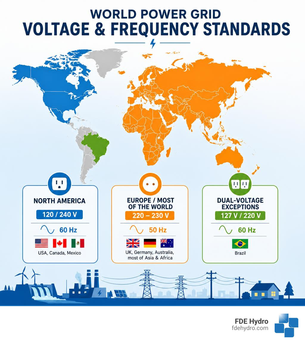
Power grid voltage — the electrical potential that drives current from generation plants to your home or facility — is not the same everywhere on Earth. In fact, two major standards divide the world:
| Region | Standard Voltage | Frequency | Example Countries |
|---|---|---|---|
| North America | 120/240 V | 60 Hz | USA, Canada, Mexico |
| Europe / Most of World | 220–230 V | 50 Hz | UK, Germany, Australia, most of Asia & Africa |
| Dual-voltage exceptions | 127 V / 220 V | 60 Hz | Brazil |
These differences trace back to the late 1800s — the famous rivalry between Thomas Edison and Nikola Tesla — when countries independently locked in their own electrical standards before any international coordination existed.
Today, those early choices still shape every power plant, transformer, and outlet on the planet.
And it’s not just about plug shapes. The voltage and frequency your grid runs at affects:
- Equipment compatibility across borders
- Transmission efficiency over long distances
- Voltage stability as renewable energy sources are added to the grid
- Safety standards for workers and consumers
The U.S. grid alone spans more than 160,000 miles of high-voltage transmission lines, connecting over 7,000 power plants to roughly 145 million customers. Managing voltage reliably across that scale — and doing it as solar, wind, and hydropower reshape the energy mix — is one of the defining engineering challenges of our time.
I’m Bill French, Sr., Founder and CEO of FDE Hydro™, and my decades of experience in heavy civil construction and hydropower infrastructure have given me a front-row seat to how power grid voltage decisions shape the design, cost, and performance of clean energy projects. In the sections ahead, we’ll break down everything you need to know — from global standards to grid stability to what it all means for modern hydropower.
Important power grid voltage terms:
What is Mains Electricity and How is It Delivered?
Mains electricity is the general-purpose alternating current (AC) electric power delivered to homes and businesses. It is the lifeblood of modern society, powering everything from our phone chargers to heavy industrial machinery.
But how does it get to your wall outlet? The process is a highly coordinated journey across multiple layers of infrastructure. To understand this complex dance, it helps to first ask: what does grid mean in electrical engineering? In short, the grid is a massive, interconnected network designed to generate, transmit, and distribute electricity over vast geographic distances.
When you flip a switch, you are drawing on a system that operates in real-time, matching supply with demand instantaneously. To explore this in action, check out these shocking examples of how the electrical grid powers our lives.
The Battle of Currents: Why We Use Alternating Current (AC)
In the late 19th century, the “War of the Currents” pitted Thomas Edison’s Direct Current (DC) against Nikola Tesla and George Westinghouse’s Alternating Current (AC). Edison’s DC systems could only transmit power effectively over a mile or two before the voltage dropped significantly due to line resistance.
Tesla’s AC system won because of a fundamental physical principle: electromagnetic induction. With AC, we can use transformers to easily step up the voltage for long-distance transmission and step it down for safe utilization.
Because transmission line losses are proportional to the square of the current ($I^2R$), raising the voltage allows us to transmit the same amount of power with much lower current, dramatically reducing energy losses over hundreds of miles. To learn more about the basic physics behind this, you can read the Electricity 101 | Department of Energy guide.
Single-Phase vs. Three-Phase Power Delivery
Once the electricity reaches your local area, it is delivered using one of two configurations:
- Single-Phase Power: Typically used for residential and light commercial applications. It delivers a single AC sine wave. In a 60 Hz system, the voltage oscillates back and forth, crossing the “zero-voltage” mark 120 times every second. While this is unnoticeable for lighting and small electronics, it is not ideal for large electric motors.
- Three-Phase Power: Used for industrial facilities, large commercial buildings, and generation plants. It consists of three separate AC sine waves offset by 120 degrees. This means that as one phase drops toward zero, another is peaking. This constant, smooth delivery of power is highly efficient for running large motors, heavy machinery, and industrial water pumps.
Demystifying Power Grid Voltage: Generation, Transmission, and Distribution Layers
To move electricity from a turbine to a toaster, the grid relies on a series of distinct layers, each operating at a specialized power grid voltage.
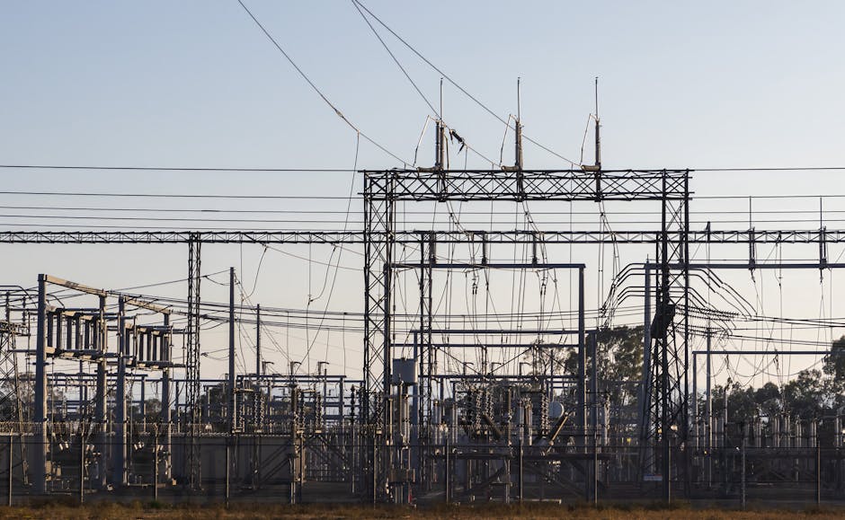
At the generation station, step-up transformers raise the voltage to extreme levels for long-distance travel. Once the electricity nears its destination, step-down transformers lower the voltage to safe, usable levels. You can explore the physical infrastructure behind this in our guide on High Voltage Lines: The Backbone of Our Power Grid.
Voltage Classifications: High, Medium, and Low Voltage
The grid is divided into four distinct operational layers, each classified by its voltage range as outlined in Power System Fundamentals: U.S. Grid Structure, Voltage Levels, and Core Studies | EleCalculator:
- Generation: Power plants (such as hydro, nuclear, or gas) typically generate electricity at medium voltages, usually between 4.16 kV and 34.5 kV. A generator step-up transformer immediately boosts this to transmission levels.
- Transmission (High Voltage): Transmission lines carry bulk power over long distances. In North America, transmission voltages typically range from 69 kV up to 765 kV. Operating at these high levels minimizes thermal losses.
- Subtransmission and Distribution (Medium Voltage): Substations step the voltage down to distribution-primary classes, which commonly range from 4.16 kV to 34.5 kV. This medium voltage travels down street-level lines (either overhead or underground).
- Utilization (Low Voltage): Finally, small distribution transformers (the grey canisters on utility poles) step the voltage down to the final utilization voltage. For residential homes in North America, this is 120/240V split-phase.
For a deeper dive into how these networks are structured structurally, see our breakdown of the various electrical networks and grid expectations.
Nominal, Service, and Utilization Voltages Explained
Engineers categorize voltage into three distinct definitions to ensure equipment functions safely and within standard parameters:
- Nominal System Voltage: The designated value assigned to a circuit or system for the purpose of convenient nomenclature (e.g., 120V, 240V, 480V).
- Service Voltage: The voltage measured at the point where the utility’s system connects to the customer’s electrical installation (the billing meter).
- Utilization Voltage: The voltage measured at the terminals of the operating equipment (the wall outlet or appliance plug).
Because of resistance in building wiring, the utilization voltage is normally slightly lower than the service voltage. National standards, such as the ANSI C84.1-1995 standard, establish strict operating tolerances. These guidelines ensure that utilities maintain service voltages within acceptable limits (typically within $pm 5%$ of nominal) so that end-user equipment is not damaged by overvoltage or starved by undervoltage.
Comparing Global Voltage Standards: Why Regions Differ
The global map of mains electricity is a patchwork of historical compromises. When grids were first constructed in the late 19th and early 20th centuries, there was no global supply chain for household appliances. Consequently, different regions adopted standards based on local engineering preferences and economic conditions.
For a comprehensive breakdown of worldwide electrical standards, you can consult the Voltage, frequency and plug type per country – Royal Brinkman database.
| Country/Region | Nominal Voltage | Frequency | Standard Plug Types |
|---|---|---|---|
| United States | 120 V | 60 Hz | Type A, Type B |
| Canada | 120 V | 60 Hz | Type A, Type B |
| Europe | 230 V | 50 Hz | Type C, Type E, Type F, Type G |
| Brazil | 127 V / 220 V | 60 Hz | Type N |
North American Standards (120V/60Hz)
North America settled on 120V at 60 Hz. This standard relies on a “split-phase” residential delivery system. The utility delivers two 120V hot wires that are 180 degrees out of phase, along with a shared neutral wire.
Standard household outlets connect one hot wire and the neutral to deliver 120V for low-power devices. For heavy appliances like clothes dryers, water heaters, and air conditioners, both hot wires are connected to deliver a full 240V.
In Canada, where more than half of the country’s electricity is generated by massive, highly efficient hydroelectric facilities, the standard remains identical to the U.S. to ensure seamless economic and equipment compatibility. Travelers can find more details about Canadian electrical currents in the Electric plug and socket type in Canada | Adapter or converter? guide.
European and Global Standards (230V/50Hz)
Europe and much of the rest of the world opted for a nominal voltage of 220–230V at a frequency of 50 Hz. The primary advantage of a higher residential voltage is efficiency. Because double the voltage requires half the current to deliver the same amount of power ($P = V times I$), European household wiring can be thinner and experiences lower internal resistive losses.
However, higher voltage carries a greater risk of severe electrical shock, which is why European countries historically developed highly robust safety standards, ground-fault protections, and heavily insulated plug designs.
Brazil represents an interesting dual-voltage hybrid. Depending on the state or municipality, the local grid might supply 127V or 220V, both running at 60 Hz. This split requires travelers and industrial developers to be highly vigilant about checking local ratings. For guidance on navigating this environment, check out the Travel Adaptor for Brazil | Electrical Safety First resource.
Grid Stability: Managing Fluctuations, Regulation, and Modern Challenges
A stable grid is a balanced grid. Both frequency and power grid voltage must be kept within strict tolerances to prevent equipment damage and grid-wide blackouts.
If the grid suffers a catastrophic failure, operators rely on specialized protocols to restore power. You can read about this emergency process in The Black Start Blueprint: How Power Grids Come Back to Life. To maintain normal, day-to-day operations, the grid also relies on a steady foundation of Base Load Power: Understanding the Grid’s Minimum Demand.
How Power Grid Voltage Fluctuations and Overvoltages Affect Equipment
Voltage levels on the grid fluctuate constantly as large loads turn on and off.
- Voltage Sags (Undervoltage): When large industrial motors start up, they draw high inrush currents, causing a temporary dip in local voltage. Severe sags can cause electric motors to overheat, computers to reset, and industrial processes to shut down.
- Transient Overvoltages (Swells and Spikes): Sudden load rejections (such as a factory shutting down) or lightning strikes can cause dramatic voltage spikes. These transients can puncture electrical insulation, destroy sensitive microelectronics, and cause electrical fires.
To combat these issues, utilities use voltage regulation equipment, including load tap changers (LTCs) on substation transformers, line-voltage regulators, and capacitor banks that inject reactive power to boost sagging voltages.
The Impact of Renewable Energy on Power Grid Voltage Stability
The transition to clean energy introduces new complexities to voltage regulation. Traditional power grids rely on massive, spinning synchronous generators (like those in coal, gas, or large hydro plants) that naturally provide physical inertia and automatic voltage regulation.
Modern wind and solar resources, however, are Inverter-Based Resources (IBRs). They interface with the grid through power electronics rather than heavy rotating machinery. This shift creates several challenges:
- Loss of Inertia: With fewer spinning generators online, the grid is more susceptible to rapid frequency and voltage deviations.
- Bidirectional Power Flow: Traditional distribution grids were designed for one-way traffic—from the high-voltage transmission system down to the low-voltage customer. High penetrations of rooftop solar can push power backward up the line, causing localized overvoltages.
- Intermittency: Sudden changes in solar irradiance or wind speed cause rapid power fluctuations, requiring highly dynamic voltage control.
To address these challenges, researchers and grid operators are turning to advanced control strategies. You can read a comprehensive analysis of these emerging issues in the Review of Challenges and Research Opportunities for Voltage Control in Smart Grids (Journal Article) | OSTI.GOV.
Additionally, technologies like smart inverters are being programmed with Volt-Var control capabilities, allowing them to dynamically absorb or inject reactive power to stabilize local voltages. For a deeper look at these techniques, see the Department of Energy’s report on Voltage Optimization.
These challenges are not theoretical. In places like New York, grid operators are facing historically thin safety margins heading into the high-demand summer months, highlighting the urgent need for rapid, reliable grid modernization.
TSO and DSO Coordination in Modern Smart Grids
As distributed energy resources (DERs) like rooftop solar and localized battery storage multiply, the boundary between the Transmission System Operator (TSO) and the Distribution System Operator (DSO) is blurring.
Traditionally, the TSO managed the high-voltage transmission system and bulk generation, while the DSO simply managed the local delivery. Today, voltage stability on the transmission system increasingly depends on the aggregate behavior of millions of small-scale resources connected to the distribution system.
Active coordination is essential. DSOs must monitor and optimize local voltage profiles, while TSOs coordinate wide-area monitoring and control schemes to ensure that local voltage adjustments do not trigger larger, cascading instabilities across the macrogrid.
Frequently Asked Questions about Power Grid Voltage
Why do different countries use different plug shapes and voltages?
Different countries built their electrical grids independently during the late 19th and early 20th centuries. By the time international travel and trade made standardization desirable, the cost of replacing millions of existing outlets, appliances, and transformers was too high. Consequently, countries stuck with their legacy standards, leading to the diverse array of plug shapes and voltages we see today.
What is the difference between service voltage and utilization voltage?
Service voltage is the electrical potential delivered by the utility to your facility’s billing meter. Utilization voltage is the actual voltage available at your wall outlets or equipment terminals. Utilization voltage is typically slightly lower than service voltage due to natural voltage drops caused by resistance in the building’s internal wiring.
Can we harness lightning to power the electrical grid?
No, we cannot. While a single lightning strike contains a massive amount of energy—approximately 1,500 megajoules (MJ), which is enough to power a 100W light bulb for nearly six months—lightning is far too brief, localized, and unpredictable. To equal the output of a standard 1-gigawatt (GW) power plant, we would need to capture and store more than 58,000 perfectly timed lightning strikes every single day. The technology required to safely capture and store such high-voltage, high-current transients in microseconds does not exist.
Conclusion
As we march toward a decarbonized future, grid modernization and voltage stability are more critical than ever. The integration of intermittent wind and solar requires a flexible, resilient grid infrastructure that can adapt to rapid changes in generation and demand.
At FDE Hydro™, we believe that hydropower has a vital role to play in this transition. Beyond producing clean, reliable baseload power, hydroelectric plants act as massive, spinning synchronous condensers that naturally stabilize power grid voltage and frequency.
To accelerate the deployment of these essential grid assets, we developed our patented modular precast concrete technology, known as the French Dam. By replacing slow, carbon-intensive, on-site concrete pouring with precision-engineered, precast modules, we dramatically reduce the construction costs and development timelines of hydroelectric projects and water control structures across North America, Brazil, and Europe.
Whether retrofitting an existing non-powered dam or building a new run-of-river facility, our technology makes clean, grid-stabilizing energy more accessible and cost-effective than ever before.
Are you interested in learning more about the engineering behind modern power systems? Explore our Power Grid Articles to stay informed on the latest trends in grid stability, renewable integration, and clean energy infrastructure.
