

Why Hydro Brake Stormwater Management Is Changing How Engineers Control Runoff
Hydro brake stormwater flow control is a technology that uses a spinning vortex — not moving parts or motors — to regulate how fast water drains from a storage area into a downstream pipe or sewer.
Here’s a quick answer to what it does and why it matters:
- What it is: A self-activating vortex device installed at the outlet of a detention tank, pond, or manhole to limit discharge rates
- How it works: As water rises, a spinning air core forms inside the device and throttles flow — automatically, without any power or mechanical components
- Key benefit: It can reduce required stormwater storage volumes by up to 40% and cut project storage costs by up to 50% compared to conventional orifice controls
- Who uses it: Civil engineers, drainage designers, and infrastructure owners managing surface water, combined sewers, or flood risk
- Certifications: Leading vortex flow control products are independently certified by bodies such as BBA and WRc
Urban stormwater systems are under growing pressure. More impervious surfaces, more intense storms, and aging combined sewers are pushing existing infrastructure to its limits. When a system surcharges, the consequences are serious — street flooding, basement backups, and combined sewer overflows (CSOs) that discharge raw sewage into waterways. Traditional orifice plates can help slow things down, but they come with a fundamental trade-off: the smaller the orifice, the greater the blockage risk, and the shallower the storage you can practically achieve. Vortex-based flow controls were developed specifically to break that trade-off.
I’m Bill French, Sr., Founder and CEO of FDE Hydro™, with five decades of experience in heavy civil construction and water infrastructure — including leading large-scale site and drainage projects across New England and contributing to the U.S. Department of Energy’s Hydropower Vision initiative. My team at FDE Hydro™ works at the intersection of modular construction and water control, and hydro brake stormwater management is a technology we see transforming how large infrastructure projects approach runoff, detention, and flood risk. In the sections ahead, we’ll break down exactly how these systems work, where they deliver the most value, and how to design and size them for your project.
Understanding the hydro brake stormwater System and How It Works
To understand why a vortex valve is such a leap forward in civil engineering, we have to look closely at fluid hydraulics. In a traditional system, flow control is passive and linear. A standard orifice plate is simply a metal sheet with a hole in it. The rate of water passing through that hole is entirely dependent on the depth of the water (the hydraulic head) pushing down on it. As the head increases, the water is forced through faster, which can surcharge downstream systems when they are at their most vulnerable.
A hydro brake stormwater system, by contrast, is a self-activating vortex valve. It operates on simple yet highly optimized fluid hydraulics without requiring external power, sensors, or moving parts.
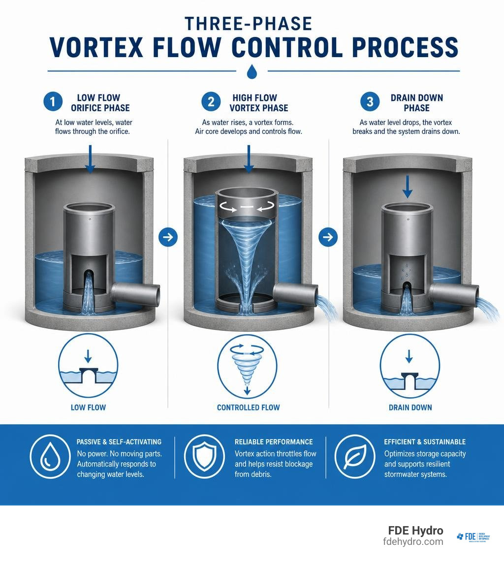
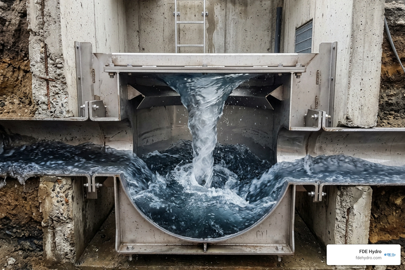
At the center of this technology is the formation of an air core. When stormwater enters the intake chamber of the device at low depths, it passes straight through, behaving like a standard, oversized pipe. However, as the water level rises and the hydraulic head increases, the geometry of the chamber forces the incoming water to spin rapidly. This rotational motion generates centrifugal force, creating a stable, air-filled vortex core in the center of the outlet.
This air core acts as a physical restriction, significantly throttling the discharge rate. By utilizing this phenomenon, the system achieves a highly controlled flow rate while maintaining a physical opening that is significantly larger than a traditional orifice plate. To dive deeper into how these components integrate into broader water management networks, you can explore our Vortex Flow Control Technology resources.
The Physics of Vortex Flow Control in hydro brake stormwater Applications
The physics of vortex flow control revolves around the relationship between velocity, pressure drop, and centrifugal force. In a standard orifice, the discharge rate ($Q$) is calculated using the standard orifice equation:
$$Q = C_d A sqrt{2gh}$$
Where $C_d$ is the discharge coefficient, $A$ is the area of the orifice, $g$ is gravity, and $h$ is the hydraulic head. To restrict flow ($Q$) at high heads ($h$), you must make the opening area ($A$) very small.
A vortex flow control device changes this equation. As water enters the vortex chamber tangentially, its velocity increases as it spirals inward toward the outlet. This high-velocity rotation creates a massive centrifugal force that pushes the water outward against the chamber walls. This action creates a low-pressure zone in the center, drawing in air through the outlet to form a stable air core.
The air core reduces the effective cross-sectional area available for water discharge. Consequently, the device creates a significant pressure drop and restricts the discharge rate without needing to physically constrict the metal opening. This allows engineers to design systems that maintain a relatively constant discharge rate once the vortex is established, regardless of how high the water rises. For a comprehensive look at how these physical principles are engineered into civil works, read our Water Control Structures Guide.
The Three Phases of hydro brake stormwater Operation
A hydro brake stormwater system operates in three distinct, automatic phases based on the hydraulic head:
- Low Flow (The Orifice Phase): During the initial stages of a storm, water depths are low. The water flows directly through the device from the inlet to the outlet without spinning. In this phase, the device behaves like a standard, oversized orifice, allowing water to drain quickly so that the storage area does not unnecessarily fill up during minor rain events.
- High Flow (The Vortex Phase): As the rain intensifies and the water level reaches a critical design point (often referred to as the “Switch-Flo” or “Kick-Flo” point), the water depth forces a tangential flow pattern inside the chamber. The water spins rapidly, the air core forms, and the device throttles the discharge. Even as the hydraulic head continues to rise to its maximum design level, the discharge rate remains tightly controlled and relatively constant.
- Drain Down Phase: Once the storm passes and the water level in the detention facility drops, the hydraulic head decreases. The centrifugal energy dissipates, the air core collapses, and the system transitions back into the high-capacity orifice mode. This allows the remaining water to drain out rapidly, ensuring the storage basin is dry and fully prepared for the next storm event.
Key Benefits of Vortex Flow Controls vs. Traditional Orifices
When designing stormwater detention facilities, municipal sewer connections, or green infrastructure projects, civil engineers face a constant battle against physical space and regulatory limits. The table below highlights the practical differences between vortex flow control systems and standard orifice plates:
| Feature | Vortex Flow Control (e.g., Hydro-Brake®) | Traditional Orifice Plate |
|---|---|---|
| Physical Opening Size | 3 to 6 times larger than equivalent orifice | Small, restricted opening |
| Blockage Risk | Very Low (due to large clear opening) | High (prone to leaves, trash, and silt) |
| Discharge Profile | Non-linear; controls flow early and maintains flat peak | Linear; discharge increases rapidly with head |
| Upstream Storage Needed | Reduced by up to 40% | Maximum storage volume required |
| Adjustability | Up to ±20% post-installation (on select models) | None (requires physical plate replacement) |
| Moving Parts / Power | None (100% self-activating) | None |
Reducing Upstream Storage Footprints
A challenge in modern urban development is footprint constraints. Whether you are designing a commercial development in California or a public transit expansion in New York City, land is expensive, and dedicating massive areas to surface dry ponds or underground concrete detention vaults can break a project’s budget.
Because a hydro brake stormwater device allows a higher discharge rate during the early and mid-stages of a storm before transitioning to vortex control, it utilizes the available downstream discharge allowance much more efficiently throughout the entire storm event. This optimized hydraulic performance allows engineers to design deeper detention systems with smaller footprints.
Using vortex technology can reduce required stormwater storage volumes by up to 40%, translating directly into up to 50% savings in project storage costs. This means less excavation, fewer precast concrete structures, and more land preserved for development. To see how these savings scale on large municipal projects, refer to our guide on Water Infrastructure Solutions.
Minimizing Blockage and Maintenance Risks
A traditional orifice plate designed for low discharge limits often requires a very small opening—sometimes less than 2 inches (50 mm) in diameter. These small openings are incredibly prone to clogging from autumn leaves, plastic bags, beverage cans, and sediment. When an orifice blocks, upstream areas flood, and maintenance crews must perform emergency clearance in dangerous, wet conditions.
Vortex flow controls solve this by maintaining a physical opening that is 3 to 6 times larger than an equivalent orifice plate designed for the exact same flow rate. Debris that would immediately clog a 2-inch orifice easily passes through the large opening of a vortex valve. Furthermore, advanced units feature an integrated bypass door. This door can be opened from ground level via a pull cable, allowing the chamber to drain completely in the event of an upstream blockage without requiring a technician to enter the manhole. Learn more about maintaining system integrity in Mastering Your Mains A Guide To Water Flow Control Devices.
Exploring Hydro Brake Stormwater Design Configurations
The Hydro-Brake Flow Control Series represents a highly versatile toolbox of precision-engineered devices tailored to meet specific site constraints, budget requirements, and discharge consents. Because no two drainage catchments are identical, these systems are configured to prioritize different performance objectives—whether that is minimizing upstream storage, handling massive floodwaters, or dropping water down deep vertical shafts.
Adjustable Vortex Flow Controls: Precision and Future-Proofing
The Hydro-Brake Optimum | Hydro International is the flagship of vortex flow control technology, drawing on more than 40 years of continuous engineering development. It is highly customizable, allowing engineers to specify the exact point at which the vortex begins for any given head and flow.
One of its most innovative features is its built-in future-proof adjustability. The unit features an adjustable inlet plate that can be modified post-installation to allow up to a ±20% change in the design flow rate without replacing the device. This is incredibly valuable for addressing long-term climate change, urban creep (increased impervious surfaces from local development), or changes in regional environmental regulations.
The Hydro-Brake ® Optimum is independently certified by the British Board of Agrément (BBA, Certification no. 08/4596) and the Water Research Centre (WRc, Certification no. PT/503/0422), giving engineers complete confidence in its hydraulic performance and structural durability. For more information on specifying adjustable water control components, see our Adjustable Flow Controls engineering resource.
Large-Scale Vortex Controls for Flood Alleviation
When managing watercourse-level flows or protecting entire communities from flooding, standard drainage controls are simply too small. The Hydro-Brake Flood | Hydro International is designed specifically for large-scale flood alleviation schemes.
These high-capacity units can handle maximum flows of up to 11,500 l/s (182,278 gpm) and maximum heads of up to 11 meters (36 feet). Operating on the same vortex principles, they temporarily hold back excess water in natural river valleys, dry reservoirs, or designated flood basins, releasing it at a safe, controlled rate into downstream watercourses. Because they have no moving parts and require no power, they provide reliable flood protection in remote locations where electrical failure during a major storm is a constant threat. Read more about large-scale water control in our Flood Alleviation Systems guide.
Specialized Vortex Flow Solutions: Energy Dissipation and Shear Gate Controls
In addition to standard surface water controls, specialized configurations exist for unique structural and hydraulic challenges:
- Vertical Drop Energy Dissipation: Dropping large volumes of water down deep vertical shafts—such as in deep tunnel sewer systems or steep hillside drainage—can cause severe noise, structural vibration, air entrainment, and pipe erosion. The Hydro-Brake Drop | Hydro International safely conveys water down drops of up to 330 feet (100 meters) and flow rates up to 5,000 l/s (10,500 ft³/min). It uses vortex action to dissipate kinetic energy against the pipe walls, eliminating cavitation and structural wear while controlling corrosive sewer gases like hydrogen sulfide.
- Constant Discharge Shear Gate Controls: For sites with incredibly strict discharge consents and highly limited space, the Hydro-Brake Agile | Hydro International offers a unique mechanical-hydraulic hybrid solution. It uses a float arm and sliding gate mechanism to maintain a completely constant discharge rate across varying water depths, minimizing the required upstream storage volume to the absolute physical minimum. Learn about these specialized systems in our guide to Specialized Flow Controls.
Design, Sizing, and Installation Considerations
Integrating a hydro brake stormwater system into a project requires careful hydraulic modeling and structural planning. Because these devices rely on the physical properties of the vortex, their head-discharge curves are non-linear, which must be accurately accounted for in drainage design software.

Sizing and Hydraulic Calculations
When sizing a vortex flow control, engineers must establish three primary parameters: the design flow rate ($Q$), the maximum allowable design head ($h$), and the available upstream storage volume.
The Hydro-Brake® Optimum supports a maximum flow of up to 550 l/s (8,717.7 gpm) and can manage drainage catchments with a maximum storage area of up to 275 hectares (assuming an average of 2 l/s per hectare for storage sizing).
Using proprietary design software or the official design tool, engineers can generate a highly customized head-discharge curve that maximizes the outflow rate during the early stages of a storm while strictly capping the peak discharge at the maximum allowable limit. This curve is then imported into standard hydraulic modeling software to size the associated retention ponds, blue roofs, or underground concrete vaults. For detailed calculations, check out the Water Control System Complete Guide.
Installation Configurations and Downstream Clearance
For a vortex flow control to function correctly, it must be installed in accordance with specific physical and hydraulic guidelines:
- Downstream Clearance: All vortex flow controls must maintain adequate downstream clearance to allow the air core to vent and the discharge jet to expand. Typically, this requires a minimum clearance of 3 meters (9.84 feet) or ten times the outlet pipe diameter (whichever is greater) with no valves, bends, or pipe diameter changes within this zone.
- Surcharge Conditions: If the downstream receiving sewer surcharges (fills completely), the backpressure can interfere with the vortex’s air core. In these installations, an air vent pipe must be extended from the device to a point above the maximum water level to ensure the air core can form under all conditions.
- Mounting Styles: Depending on the chamber design, units can be specified in wall-mounted configurations (bolted directly over the outlet pipe on a flat concrete headwall), floor-mounted configurations, or pre-installed inside a precast concrete manhole chamber for rapid site installation.
Integrating Vortex Flow Controls with SuDS and Green Infrastructure
Modern urban planning emphasizes Sustainable Drainage Systems (SuDS), Low-Impact Development (LID), and green infrastructure. Rather than routing stormwater into massive concrete pipes as quickly as possible, the goal is to mimic natural hydrology by capturing, filtering, and releasing water slowly.
Vortex flow controls are a natural fit for green infrastructure:
- Bioretention Cells and Rain Gardens: By installing a small vortex valve at the outlet of a bioretention basin, you can maximize the water depth and contact time within the soil and vegetation layer, improving pollutant filtration without risking downstream flooding.
- Blue Roofs: In dense urban areas like New York City or San Francisco, roofs are increasingly being used as temporary stormwater detention basins. A vortex control limits the drain-down rate of the roof, allowing shallow ponding that evaporates or drains slowly over 24 to 48 hours.
- California Stormwater Treatment: In regions with strict water quality regulations, such as those detailed in California Stormwater Treatment | Hydro International , vortex flow controls are used to regulate the flow of runoff entering treatment trains, ensuring that oil-grit separators and media filters operate within their optimal design flow rates.
By carefully regulating water quantity, these devices protect expensive green infrastructure assets from erosion and washouts during extreme weather events. Learn more about designing for long-term sustainability in our guide to Sustainable Water Infrastructure.
Frequently Asked Questions about Hydro Brake Stormwater Systems
How does a hydro brake stormwater system prevent blockages compared to a standard orifice?
A standard orifice plate restricts flow by physically reducing the size of the opening. To achieve low flow rates, the opening must be very small (often 2 inches or less), which easily traps leaves, twigs, and litter. A vortex flow control restricts flow dynamically using centrifugal force and an air core. This allows the physical opening of the device to be 3 to 6 times larger than an equivalent orifice plate, allowing debris to pass through easily without causing a blockage.
Can a hydro brake stormwater device be adjusted after installation?
Yes, select models like the Hydro-Brake® Optimum feature an adjustable inlet plate. This plate can be adjusted post-installation to increase or decrease the design flow rate by up to ±20%. This built-in flexibility allows engineers to adapt the system to future site developments, changing climate patterns, or updated municipal regulations without having to excavate and replace the entire flow control unit.
What are the maintenance requirements for these vortex flow control systems?
Because vortex valves have no moving parts and rely entirely on simple fluid hydraulics, they are virtually maintenance-free. Maintenance typically consists of periodic visual inspections (usually twice a year) to remove any large debris or silt accumulation from the floor of the concrete chamber. Many units also feature a manual bypass door operated via a pull cable from ground level, allowing maintenance crews to safely drain the chamber in an emergency without entering the manhole.
Conclusion
Managing urban runoff requires a careful balance of hydraulic performance, structural footprint, and long-term reliability. Traditional orifice plates, while simple, place a heavy burden on projects by requiring larger detention footprints and presenting a constant risk of blockage and maintenance failure. Hydro brake stormwater systems break this bottleneck, utilizing the natural physics of vortex flow to restrict discharge safely, reduce required storage volumes by up to 40%, and lower overall project costs.
At FDE Hydro™, we believe that the future of water management lies in combining smart hydraulic technologies with innovative, rapidly deployable construction methods. Our patented modular precast concrete technology is designed to streamline the installation of heavy civil water control structures, dams, and municipal containment chambers, significantly reducing construction timelines and costs across North America, Brazil, and Europe.
Whether you are designing a complex urban retrofitting project in New York, a green infrastructure development in California, or a municipal CSO mitigation system in Canada, pairing advanced vortex flow control with modular precast structures ensures your project is built to last, fully compliant, and highly cost-effective.
Ready to optimize your next water control project? Explore our comprehensive Water Control Solutions Complete Guide or contact our engineering team today to discuss how we can streamline your infrastructure design.
