

The Layer of the Grid That Powers Almost Everything
The medium voltage grid is the critical middle layer of the electrical power system — sitting between the high-voltage transmission lines that carry electricity across long distances and the low-voltage lines that deliver power to homes and small businesses.
Here’s a quick answer if that’s what you need:
| Question | Answer |
|---|---|
| What is a medium voltage grid? | The distribution network segment operating between 1 kV and 36 kV (IEC standard) |
| Where does it fit? | Between high-voltage transmission and low-voltage end-user supply |
| Who uses it directly? | Factories, hospitals, airports, water plants, large campuses, and renewable energy farms |
| Why does it matter? | It carries power to nearly every major load center — and distribution failures cause 92% of all U.S. power outages |
| What’s the U.S. average? | Around 13 kV, across roughly 5.5 million miles of local distribution lines |
Think of the power system as a river system. High-voltage transmission lines are the wide, fast-moving main river. The medium voltage grid is the network of tributaries branching off to reach communities and industries. Low-voltage lines are the final small streams that reach your front door.
That middle layer — the medium voltage grid — is where most of the action happens. It’s where renewable energy sources connect, where large industrial customers tap in, and where the vast majority of outages originate. Unreliable electricity at this level costs U.S. customers an estimated $85 billion every year.
In 2026, with renewable energy generation expanding rapidly and aging grid infrastructure under growing pressure, understanding how this layer works has never been more important — especially for infrastructure developers and project owners making high-stakes decisions about grid connection and power delivery.
I’m Bill French, Sr., Founder and CEO of FDE Hydro™, and over decades of delivering large-scale civil and energy infrastructure — including run-of-river hydropower facilities that connect directly to the medium voltage grid — I’ve seen how grid architecture shapes project viability and long-term performance. In this guide, I’ll walk you through everything you need to know about how the medium voltage grid works, what’s in it, and where it’s headed.
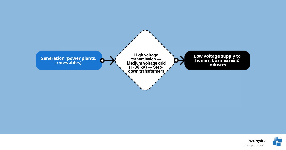
Medium voltage grid terminology:
What Is a Medium Voltage Grid and Where Does It Sit in the Power System?
A medium voltage grid is the part of the power system that moves electricity from bulk transmission substations toward neighborhoods, commercial districts, industrial sites, community infrastructure, and utility-scale renewable projects. If you want a broader refresher on grid layers, see More on electrical networks.
In practical terms, this is the distribution backbone. It is not the continent-spanning transmission network, and it is not the final low-voltage service line to a house. It is the middle ground that makes both of those layers useful.
How medium voltage is defined
The most widely cited international definition places medium voltage between 1 kV and 36 kV. In practice, utilities may use classes such as 4.16 kV, 12.47 kV, 13.2 kV, 13.8 kV, 15 kV, 24.9 kV, 27 kV, or 34.5 kV depending on local standards and legacy equipment.
Some sources use 1-35 kV and others use 1-36 kV. That difference is mostly about convention rather than physics. The important point is that medium voltage sits well above end-use building voltage and well below transmission-level voltage.
How the medium voltage grid connects transmission to low voltage
Electricity usually follows this chain:
- Generation plant produces power.
- Transformers step voltage up for long-distance transmission.
- Transmission substations step voltage down to medium voltage.
- Medium-voltage feeders carry power through cities, towns, rural service territories, and industrial corridors.
- Local distribution transformers step power down again to low voltage for homes and small businesses.
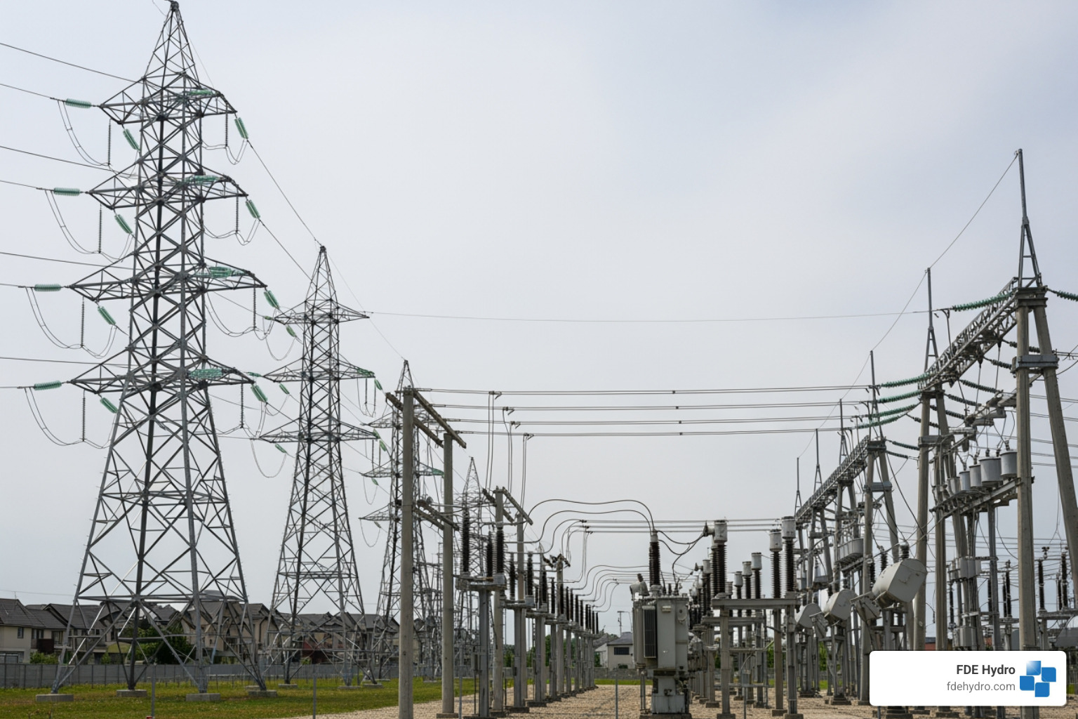
A feeder may leave an HV/MV substation and run for miles overhead in rural areas or underground in dense urban areas. Along the way, it supplies pad-mounted transformers, pole-top transformers, switchgear, and branch circuits.
High vs medium vs low voltage at a glance
| Grid layer | Typical role | Typical voltage range | Best for | Typical users |
|---|---|---|---|---|
| High voltage | Bulk transmission | Above medium voltage classes, often 69 kV and far higher in utility systems | Long distances with lower losses | Regional transmission operators, interties, large substations |
| Medium voltage | Primary distribution | 1 kV to 36 kV | Moving power across communities and to large loads | Factories, hospitals, airports, campuses, renewable plants |
| Low voltage | Final utilization | Building service and end-use voltage | Safe end-user delivery | Homes, small shops, offices |
Why the different layers? Because higher voltage reduces current for the same power transfer, and lower current means lower losses and smaller conductors for long distances. But you would not want transmission voltage showing up at your toaster. Or your coffee maker would become a space program.
Core Components of a Modern Medium Voltage Grid
The medium voltage grid depends on a mix of electrical and control equipment that keeps power flowing safely and reliably. A useful technical overview of one major equipment class is this Medium-voltage switchgear overview.
Substations, feeders, and transformer stations
At the core are substations and feeders:
- HV/MV substations step transmission voltage down to distribution voltage
- Busbars distribute power inside the substation
- Feeders carry medium-voltage power outward
- MV/LV transformer stations step voltage down for final local service
- Sectionalizing points divide networks into controllable segments
Common feeder layouts include:
- Radial feeders: simple and common, especially where cost matters
- Ring networks: offer alternate supply paths and better service continuity
- Looped arrangements with normally open points: a practical compromise between cost and reliability
Transformer stations are often the most visible sign of the medium-voltage system in built-up areas, especially where cables are underground.
Protection, control, and automation equipment
Modern MV networks rely on more than wires and transformers. They also need brains.
Key equipment includes:
- Circuit breakers
- Reclosers
- Ring main units
- Protection relays
- Fault indicators
- Voltage regulators
- Capacitor banks
- SCADA and communications equipment
- Sensors for current, temperature, and line condition
- Cable terminations and joints
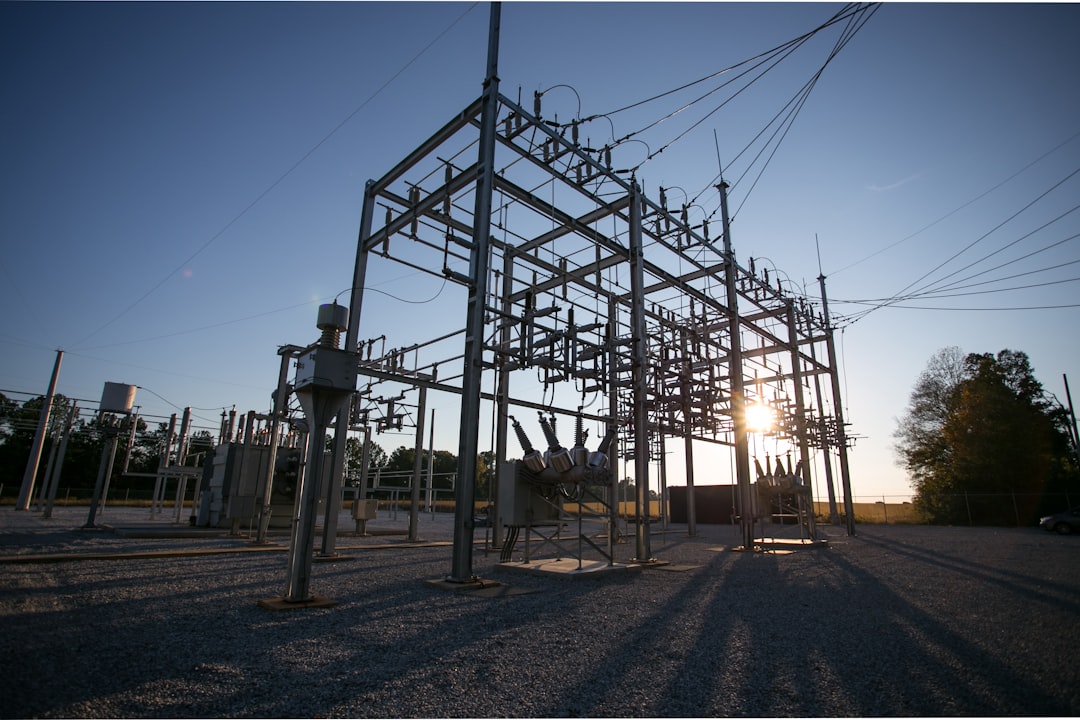
Protection coordination is crucial. If a fault occurs, the utility wants the device closest to the problem to isolate it first, while keeping healthy parts of the feeder energized. That is why relays, breaker settings, and recloser timing matter so much.
Automation adds speed. Utilities increasingly use advanced distribution management systems to support fault location, isolation, and service restoration. A smart feeder can often restore many customers automatically after a fault by switching around the damaged section.
Overhead vs underground medium voltage networks
Both overhead and underground MV systems are common, and each has tradeoffs.
Overhead networks:
- Lower installation cost
- Easier visual inspection
- Faster access for some repairs
- More exposure to storms, wind, ice, and vegetation
Underground networks:
- Better protection from weather and falling trees
- Often preferred in dense urban or visually sensitive areas
- Higher installation cost
- Fault location and repair can be slower and more specialized
In North America, both approaches are used depending on terrain, density, weather risk, and budget. In major cities, undergrounding is common. In rural service territories, overhead feeders remain widespread.
Medium Voltage Grid Applications, Customers, and Renewable Integration
A medium voltage grid does not just serve neighborhoods. It is also the connection point for many of the loads and resources shaping the modern energy system. For related distributed-control thinking, see Microgrid optimization basics.
Typical direct or near-direct MV users include:
- Manufacturing plants
- Hospitals
- Airports
- Universities and large campuses
- Water and wastewater facilities
- Data centers
- Transit systems
- Community microgrids
- Renewable energy projects
- Hydropower facilities
How PV, wind, and hydropower connect to the medium voltage grid
Solar PV plants, wind projects, battery systems, and many small hydro installations often connect at medium voltage through a point of interconnection. The general path looks like this:
- Generation is produced at the plant.
- Inverters or generator step-up transformers raise voltage to an MV class.
- A collector system gathers output from multiple units if needed.
- Protection, metering, and switching equipment interface with the utility feeder or substation.
- Utility studies confirm export limits, fault current impacts, voltage performance, and protection coordination.
For PV and battery projects, inverter behavior matters a lot. For wind and hydropower, generator controls and transformer design also matter. In all cases, the utility wants to know how the plant behaves during faults, voltage fluctuations, and restoration events.
At FDE Hydro, this is especially relevant for run-of-river and water-control infrastructure. Hydropower projects frequently connect at medium voltage because the power level is too large for ordinary low-voltage service but not large enough to justify transmission-class interconnection.
Why medium voltage is used for large loads and community-scale supply
Medium voltage is the sweet spot for customers that need substantial power without building their own transmission network.
Examples include:
- Hospitals that need strong reliability and backup integration
- Airports with extensive lighting, HVAC, and operations loads
- Water plants with large pumps and motors
- Industrial sites with process equipment
- EV charging hubs with major coincident demand
- Campuses that distribute power across multiple buildings
Using MV reduces current compared with low-voltage supply for the same power, which can reduce conductor size and losses across a facility or district.
Power quality impacts from renewable-heavy feeders
As more DERs connect to feeders, power quality becomes more dynamic.
Common issues include:
- Voltage rise during strong solar output
- Flicker from variable generation or motor loads
- Harmonics from inverter-based resources
- Reverse power flow toward upstream substations
- Phase imbalance and voltage asymmetry
- Protection miscoordination if fault current patterns change
Research on asymmetry in renewable-rich MV networks has shown that load conditions can materially change zero-voltage asymmetry, and ignoring load can produce meaningful calculation errors. If you want the technical study, see Research on asymmetry in MV networks with renewables.
The takeaway is simple: renewable integration is not just about adding megawatts. It is also about managing feeder behavior in real time.
Reliability, Safety, and Power Quality Challenges in Medium Voltage Networks
The distribution layer is where customers feel the grid most directly. And it is also where many of the problems live. For a broader everyday perspective, see How grids power daily life.
Why medium voltage grid reliability matters
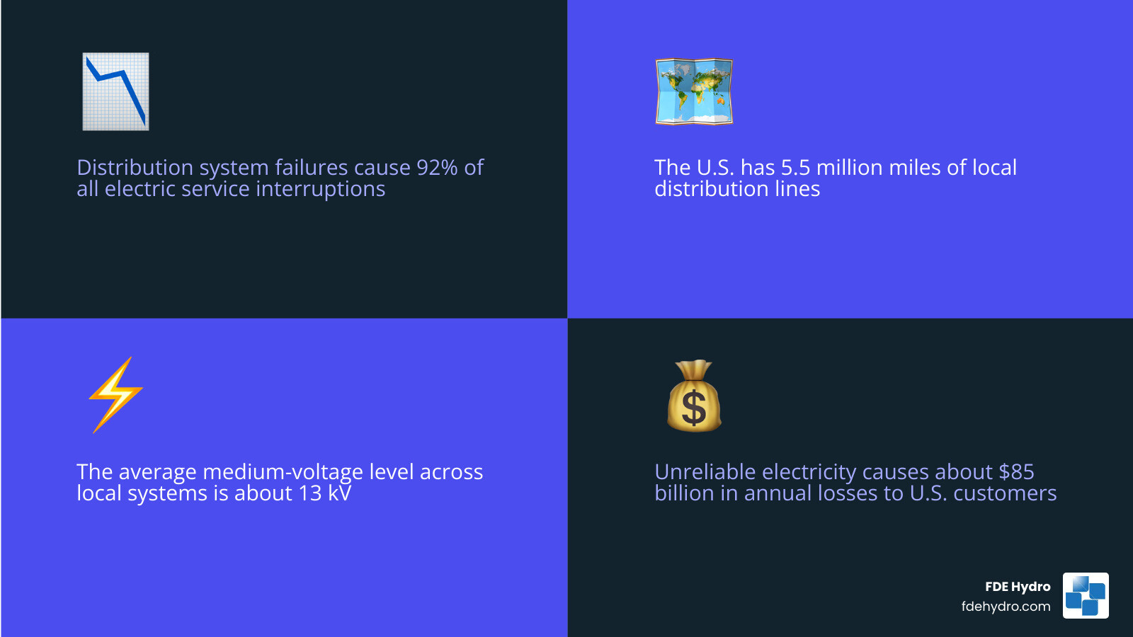
One of the most striking U.S. statistics is that distribution system failures account for 92% of all electric service interruptions. That makes the medium voltage grid a reliability front line, not a side note.
A few more important figures from the research:
- The U.S. has about 5.5 million miles of local distribution lines
- The average medium-voltage level across these local distribution systems is about 13 kV
- Unreliable electricity causes about $85 billion in annual losses to U.S. residential and business customers
Reliability challenges often include:
- Aging poles, cables, and insulation
- Extreme weather
- Vegetation contact
- Animal intrusion
- Equipment overheating
- Feeder congestion from load growth
- Limited visibility on lightly monitored circuits
Restoration time matters too. A short outage at a residence is inconvenient. A short outage at a hospital, water plant, or industrial process can be expensive or dangerous.
Safety issues in medium voltage operations
Medium voltage is not forgiving. Utility crews, contractors, and facility operators treat it with strict procedures for good reason.
Core safety concerns include:
- Arc flash risk
- Induced voltage and backfeed
- Improper switching sequences
- Inadequate grounding and bonding
- Failed insulation
- Public contact hazards after storms
- Step and touch potential near faults
Safe operation depends on:
- Lockout/tagout procedures
- Confirmed de-energization
- Proper earthing and grounding
- Qualified personnel
- Adequate approach distances and clearances
- Tested PPE and insulated tools
- Clear switching plans and communications
This is especially important as DERs increase. A line that looks de-energized from the utility side may still be energized by local generation if interconnection and isolation are not handled correctly.
Power quality problems and how utilities manage them
Power quality issues in MV networks show up as equipment stress, nuisance trips, losses, and customer complaints. Utilities manage them through both planning and active control.
Common medium-voltage faults and disturbances include:
- Single-line-to-ground faults
- Phase-to-phase faults
- Three-phase faults
- Cable insulation breakdown
- Transformer failures
- Broken conductors
- Reclosing misoperations
- Sustained undervoltage or overvoltage
- Harmonic distortion
- Voltage unbalance
Typical mitigation tools include:
- Capacitor banks for reactive support
- Voltage regulators and load tap changers
- Feeder reconfiguration
- Harmonic filtering
- Phase balancing
- Better relay settings
- Power quality monitoring
- Faster fault indicators and line sensors
The more variable the feeder, the more valuable measurement becomes. You cannot fix what you cannot see.
The Future of the Medium Voltage Grid: Smart Grids, Power Electronics, and MVDC
The future medium voltage grid will be more digital, more flexible, and more power-electronics-heavy than the one utilities built decades ago. If you want a conceptual companion piece, see What the grid means in electrical engineering.
How smart grid technologies are upgrading the medium voltage grid
Smart grid upgrades are making MV networks more observable and more controllable.
Important technologies include:
- Line sensors
- Fault passage indicators
- Smart switches and reclosers
- Advanced metering data integration
- SCADA expansion
- ADMS platforms
- Predictive maintenance analytics
- Dynamic line monitoring
- Distributed energy resource management systems
This matters because utilities need real-time visibility into feeder loading, abnormal conditions, and switching status. Research cited in the background also notes that sensor-driven approaches can improve reliability metrics such as SAIDI and reduce outage-related costs by helping utilities spot trouble earlier.
Smart grid modernization also supports DER orchestration, where utilities coordinate solar, batteries, controllable loads, and microgrids rather than treating them as passive attachments.
Cybersecurity belongs in this conversation too. The more connected the field device, the more important secure communications, authentication, patching, and network segmentation become.
The role of medium voltage power electronics
Medium-voltage power electronics are becoming a major enabler of modernization.
Examples include:
- Static VAR support and reactive compensation
- Solid-state transformers
- Back-to-back converters between networks
- Fast voltage support for weak feeders
- Interfaces for batteries and renewables
- Power flow control devices
Wide-bandgap devices such as silicon carbide are especially important because they support higher-efficiency, faster-switching converter designs. Research in this area points to the possibility of direct connection to 15-kV-class grids in some applications without a bulky line-frequency transformer.
That opens the door to more compact and intelligent grid interfaces, though deployment still depends on cost, standards, and utility acceptance.
Where MVDC fits in future distribution architecture
Most medium-voltage networks today are AC. That is still the dominant reality in 2026. But MVDC is getting more attention for niche and emerging applications.
Two useful resources are Medium-voltage direct current explained and Technical overview of MVDC systems.
Potential MVDC use cases include:
- Remote load connections
- Islanded or weak-grid systems
- Renewable collection systems
- Fast charging corridors
- Industrial DC loads
- Interfacing different grid conditions
- Black start support in certain architectures
Research summarized in the source material suggests MVDC can increase transfer capability on some converted assets and may serve projects up to roughly 150 MW in suitable cases. It is promising, but it is not yet the default answer for ordinary distribution planning. Think of it as an important tool in the future toolbox, not a magic wand.
Frequently Asked Questions About the Medium Voltage Grid
What voltage is considered medium voltage?
Most widely, medium voltage is defined as 1 kV to 36 kV under IEC-style classification. In utility practice, many common systems fall in the 4 kV to 35 kV range, with around 13 kV being a familiar U.S. distribution class.
Is the medium voltage grid AC or DC?
Today, the medium voltage grid is overwhelmingly AC. That is the standard form for utility distribution feeders and substations. However, MVDC is emerging for selected applications where power electronics and controllability offer a strong advantage.
Can renewable energy connect directly to medium voltage?
Yes. Solar farms, wind projects, battery storage, and many hydropower facilities commonly interconnect at medium voltage. They typically need inverters or step-up transformers, utility protection review, metering, switching equipment, and interconnection studies covering voltage, fault duty, export limits, and power quality.
Conclusion
The medium voltage grid is the working middle of the electric system. It links transmission to end users, serves major facilities directly, and acts as the main entry point for many renewable resources. It generally operates between 1 kV and 36 kV, often around 13 kV in U.S. distribution practice, and it carries an outsized share of reliability, safety, and modernization challenges.
It is also where the opportunity is.
As utilities expand renewable integration, electrify transportation, harden systems against extreme weather, and digitize operations, medium-voltage networks will keep getting smarter and more dynamic. Better protection, better sensing, stronger automation, and targeted use of power electronics will shape that transition.
For us at FDE Hydro, this matters because energy infrastructure does not stop at the generating asset. Whether we are talking about hydropower, water-control systems, or broader grid-connected renewable development, project success depends on understanding the grid layer that actually delivers and accepts power.
To keep exploring the topic, Browse more power grid articles.
